
Steering and suspension technical guide
Ball joints, tie rods, struts, and wheel bearings need separate tests within one chassis diagnosis
A clunk, hum, loose steering feel, pull, vibration, uneven tire wear, or unstable ride can travel through the tire, wheel, hub, knuckle, steering linkage, suspension, brake, axle, and body. Parts located at the same corner can imitate one another. A safe repair decision defines the exact operating condition, supports the vehicle correctly, measures the suspect relationship using the vehicle procedure, and verifies alignment and electronic functions after the work.
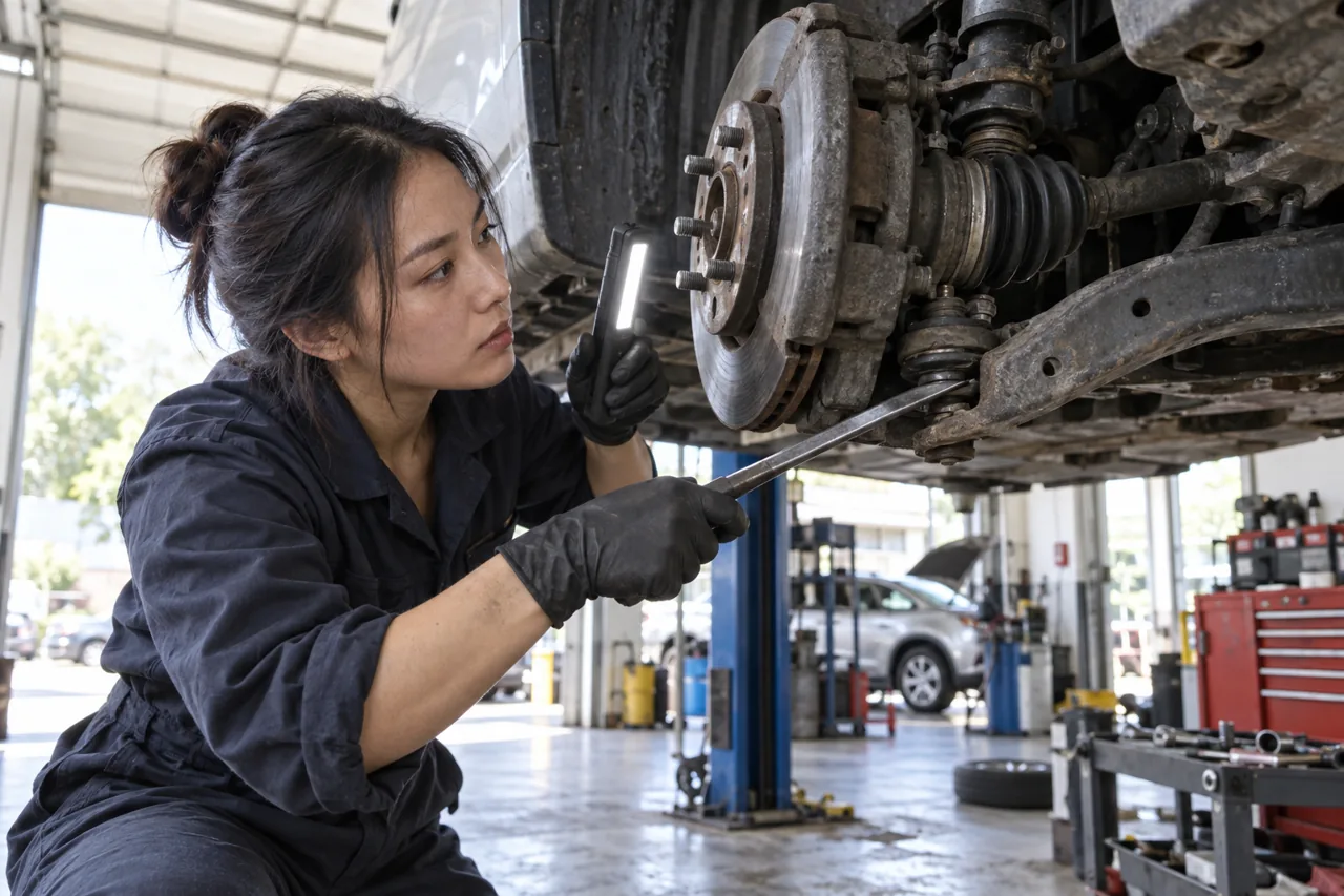
Treat loss of control, separation risk, and severe instability as urgent
Stop safely and arrange recovery when steering direction cannot be controlled normally, a wheel changes position visibly, a joint or fastener appears separated, a tire rubs structure, a corner collapses, a wheel becomes extremely loose or hot, or vibration and noise become severe. Ball-joint or tie-rod separation can remove wheel control; bearing or retention failure can damage the hub and wheel end. Do not continue simply because the vehicle still moves at low speed.
A red steering or suspension warning, sudden change after a pothole or collision, cracked spring, displaced strut, loose wheel, leaking air suspension that cannot hold safe height, or grinding combined with play requires direct assessment. Check the exact VIN for open safety recalls through NHTSA. Recall repair and ordinary diagnosis are different processes; an educational symptom list cannot determine whether a particular vehicle is included or safe to drive.
Reproduce the symptom and identify the force that changes it
Record road speed, surface, steering angle, braking, acceleration or coast, vehicle load, wind, temperature, and whether the concern occurs over small sharp bumps, large body motions, repeated undulations, lane changes, parking maneuvers, or straight travel. Note whether the sound reaches the steering wheel, seat, floor, or body and whether one wheel recently struck a curb, pothole, debris, or underwent tire, brake, axle, alignment, or suspension work.
A clunk over a bump differs from a click during steering, a speed-related hum, a brake-dependent scrape, or an engine-speed vibration. Safely compare left and right turns, load transfer, brake application, and different road surfaces only when control is not in doubt. Preserve tire wear, ride height, warning codes, alignment data, and fastener position before parts are disturbed because disassembly can remove the evidence that distinguishes a joint, mount, bearing, brake, tire, or installation fault.
Inspect the whole corner before isolating one component
Begin with tire pressure, tread and structural condition, wheel damage and retention, ride height, spring position, visible collision or corrosion, brake drag, hose and sensor routing, axle boots, control arms, bushings, stabilizer links, ball joints, tie rods, steering gear connections, shock or strut body, upper mount, bump stop, dust protection, hub, bearing, and knuckle. Compare both sides without assuming symmetry proves condition.
Look for torn boots, lost grease, water or dirt entry, rust trails, bright movement marks, displaced tapers, loose or missing hardware, cracked rubber, separated bushings, bent rods, leaking air lines, damaged electronic dampers, broken coils, tire contact, and prior modification. Visual condition guides testing but does not replace it. A clean boot does not prove a joint is tight, and surface oil on a damper must be distinguished from significant leakage using the manufacturer’s criteria.
Ball-joint inspection depends on suspension design and load state
A ball joint allows steering and suspension movement while controlling the knuckle’s position. Some are load carrying; others follow movement. Some designs permit specified movement, while others should have essentially none. The correct lift point and whether the spring load must be supported or removed determine whether wear can be felt or measured. A generic pry-bar or tire-rocking method can hide movement, load the wrong joint, or damage a boot.
Use the exact service procedure and limit, then identify vertical, axial, radial, or rotational movement with an appropriate dial indicator or controlled input when required. Separate ball-joint play from wheel-bearing movement, control-arm bushing compliance, loose fasteners, and steering linkage. Inspect the stud, housing, boot, lubrication provision, control arm, knuckle taper and retention. A torn boot is evidence of lost protection; the repair decision should also consider contamination, joint condition, available service configuration, and applicable recall instructions.
Tie-rod tests must cover inner and outer joints plus the steering path
Tie rods transfer steering-gear movement to the knuckle and help establish toe. Outer joints use a tapered stud on many vehicles; inner joints may be concealed by a rack boot. Observe and feel each interface while a controlled steering input is applied, separating movement in the inner socket, outer socket, rack, gear, column, idler or pitman arrangement, wheel bearing, ball joint, and compliant mounting. Do not diagnose an outer end from steering-wheel play alone.
Inspect boots, grease or water entry, bent rods, adjusting sleeves, jam nuts, threads, rack bellows, gear mounts, knuckle taper and fasteners. A boot filled with power-steering fluid can indicate a rack seal concern rather than tie-rod grease. Counted turns or paint marks can approximate the previous setting during assembly but are not an alignment. If movement, collision, corrosion, seized adjustment, or taper damage is present, define the complete related scope before promising a toe adjustment.
Shocks and struts control motion but do not carry every suspension function alike
A shock absorber primarily damps spring movement; a strut may also locate the knuckle and carry steering, spring, and alignment loads depending on design. Poor control can appear as excessive bounce, float, pitch, roll, bottoming, harshness, instability on rough roads, or cupped tire wear. Those symptoms can also involve tires, pressure, springs, bushings, mounts, stabilizers, ride height, alignment, electronic controls, or structure.
Monroe recommends combining operating history, road evaluation, and physical inspection. Inspect the rod, body, seals, mounts, bearings, bushings, spring and seats, isolators, bump stops, dust protection, brackets, hoses and wiring. Distinguish light weepage from leakage using the component guidance. A simple bounce test cannot prove internal damping across road speeds, and mileage alone is not a measured failure. Electronic, adaptive, air, and self-leveling units require codes, commands, height data, leak checks, power and communication diagnosis.
Wheel-bearing diagnosis separates road noise, tire noise, brakes, and driveline
A damaged bearing may hum, growl, grind, produce roughness or play, and change under cornering load, but Timken notes that clicking, clunking, and vibration can also involve CV joints, U-joints, differential backlash, tires, alignment, suspension, or wheel-end components. Tire tread pattern and road surface often imitate a bearing. Rotate or cross-check tires when appropriate, compare frequency with road speed, and identify whether braking or drive torque changes the concern.
With the vehicle safely supported according to its procedure, inspect wheel movement, rotation, roughness, noise, runout, heat, axle retention, hub and knuckle condition. Brake pads and seals can create drag, while some hub damage produces noise without easily felt play. A stethoscope, chassis microphones, lift run, temperature comparison, dial indicator, or loaded road test may help, but each has safety and interpretation limits. Never run driven wheels unsupported in a manner the vehicle or lift procedure forbids.
Movement must be traced before a part is condemned
Hands at twelve-and-six or three-and-nine can reveal movement, but the observed motion must be watched at every joint. Twelve-and-six movement can involve a bearing, ball joint or bushing; three-and-nine can involve a bearing, tie rod, rack or steering linkage. Brake application may alter bearing play on some designs, but it is not a universal discriminator. Use a helper, indicator, lever or loaded fixture only through the correct procedure.
Record the measured value, units, direction, loading method and applicable limit. “Loose” without identifying the interface and reference is weak evidence. Also inspect subframe position, control-arm mounts, wheel fasteners, hub-to-knuckle mounting, axle nut retention, steering-gear mounts, and collision damage. Several small movements can combine into poor control even when no single visual observation looks dramatic, while designed bushing compliance should not be mislabeled as failure.
Repair scope includes mating parts, one-time hardware, and installation position
Ball joints may be serviced separately, pressed into an arm, retained by fasteners, or supplied only with a control arm. Tie rods may require inner and outer tools, boots, clamps and steering-gear precautions. A strut job may involve a complete assembly or reuse of an inspected spring, mount, bearing, isolators and protection parts. Wheel bearings may be adjustable, press-fit, integrated with a hub, contain an ABS encoder, or require replacement of a knuckle or damaged hub.
Specify the exact side and axle, parts included, paired replacement rationale if any, springs or mounts, seals, clips, sensor rings, shields, axle or taper nuts, cotter pins, bolts, adhesives, lubrication, and corrosion repair. Inspect every tapered receiving hole after separation; MOOG warns that improper fit or torque can distort the taper and allow movement. Press bearing forces only through the correct race, orient an encoded seal correctly, and tighten rubber-bushed pivots at the specified position when required.
Torque, clamping, and retention are functional parts of the repair
Use the specified fastener, preparation, sequence, torque and angle. Do not substitute an impact setting, add washers to compensate for a damaged taper, reuse a prevailing-torque or staked nut when replacement is required, or apply lubricant or thread product without authorization. Under-clamping can permit movement; over-tightening can stretch hardware, damage a taper or bearing, and change joint operation. Axle-nut torque can directly affect hub-bearing preload or retention.
Support components so hoses and wiring are not stretched, protect CV joints and seals, and keep mating faces clean. Spring and strut work stores substantial energy and requires suitable equipment and positioning. Air or electronic suspension may require disable, pressure-release, ride-height or initialization procedures. Before lowering the vehicle, confirm every fastener, cotter or locking feature, routing clip, brake component, wheel-speed sensor, axle, shield and wheel attachment disturbed by the work.
Alignment and calibration follow geometry-changing work
Tie-rod, ball-joint, control-arm, strut, spring, knuckle, subframe, steering-gear and ride-height work can change toe, camber, caster, thrust angle, steering-wheel center or sensor references. Inspect tire and chassis condition and establish correct ride height before final measurement. An alignment cannot hold if a joint is loose, a spring is broken, a wheel is bent, tire pressure is wrong, or adjustment hardware cannot clamp securely.
Record before and after angles with the correct vehicle setup and load conditions. Center the steering system and complete steering-angle, yaw, ride-height, active suspension, end-stop, stability-control or driver-assistance calibration when specified. A green alignment screen alone does not prove the repaired joint is secure or that driver-assistance aim is correct; the completed process must include mechanical inspection and relevant module status.
Verification repeats the original condition and checks connected systems
After repair, confirm ride height, wheel and axle retention, free steering and suspension movement, secure boots and clamps, no hose or harness stretch, no leakage, correct tire pressure, alignment and calibrations, and normal warning status. Recheck fasteners only where the procedure requires it; indiscriminate retorquing can disturb torque-angle or one-time hardware. Scan related steering, brake, stability, suspension and driver-assistance modules when the repair affects their inputs.
Road-test over the relevant speed, surface, steering, braking, acceleration and load conditions when safe. Verify straight tracking, steering-wheel center and return, consistent effort, stable body control, absence of the original noise or vibration, normal ABS and stability behavior, and no new tire contact. Explain the confirmed fault, measurements, installed scope, alignment and calibration evidence, remaining observations and monitor triggers. A quiet short drive is not enough when the original concern required heat, speed, load or rough-road operation.