
Brake and stability-system guide
An ABS sensor code identifies a wheel-speed signal problem—not automatically a failed sensor
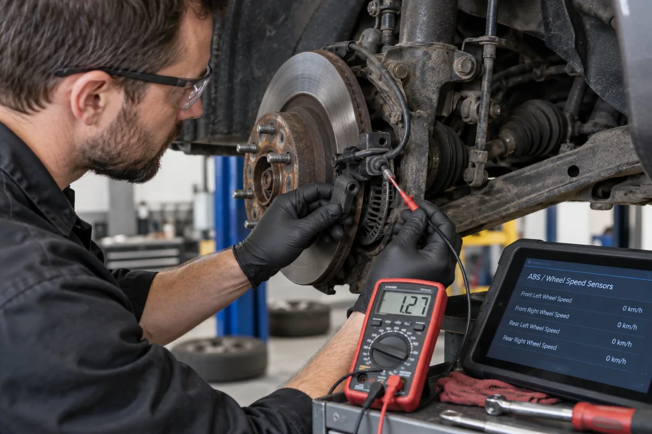
Wheel-speed information supports antilock braking, traction control, stability control, and other networked functions. A warning or code can result from the sensor, supply or ground, wiring, connector, installation gap, encoder or tone ring, wheel bearing, tire differences, module input, mechanical condition, or calibration. Diagnosis should compare the complete relationship before replacing a part.
Treat braking changes and red warnings differently from an amber ABS warning alone
Stop safely and arrange recovery for a red brake warning that remains on, a pedal that sinks or becomes unusually hard, major fluid loss, severe pulling, grinding with reduced braking, smoke, or a meaningful increase in stopping distance. An amber ABS or stability warning may indicate that an electronic assistance function is unavailable while basic hydraulic braking remains, but the exact warning combination and safe response are vehicle-specific.
Record every illuminated symbol and message, when it appeared, road speed, weather, wheel slip, steering angle, recent tire, bearing, brake, battery, alignment, collision, or suspension work, and whether restarting changes it. Do not deliberately trigger ABS on public roads to test the system. Use the owner’s manual and qualified diagnosis when normal braking or vehicle stability is uncertain.
Understand what the wheel-speed signal controls
Bosch describes a sensor at each wheel sending rotational speed to the ABS control unit, which can reduce and restore hydraulic pressure at an individual wheel when lock tendency is detected. The same information may also support traction control, electronic stability control, hill functions, all-wheel-drive strategy, transmission behavior, speed display, tire-pressure inference, parking systems, and driver assistance depending on the vehicle.
Because the signal is shared, one implausible wheel can create several warnings without several independent failures. A system that disables intervention after detecting bad data is different from unwanted intervention caused by an intermittent or distorted signal. Describe whether warnings are constant, appear only after moving, occur during a turn, or coincide with low-speed pulsing or braking intervention.
Identify active and passive sensor designs before testing
HELLA distinguishes passive inductive sensors, which generate an alternating signal from a toothed impulse wheel, from active sensors with supplied electronics that read a multipole magnetic ring or other encoder and transmit a conditioned signal. Active sensors can report very low speed and sometimes direction. Their power, ground, signal, and test behavior differ from a simple inductive winding.
Do not apply a generic resistance test, test light, magnetic probe, or voltage expectation to an unknown design. HELLA specifically notes that internal resistance cannot be measured on active sensors. Use the exact wiring diagram, pin information, signal description, approved breakout method, and suitable meter, oscilloscope, or scan tool. Poor probing can spread terminals, damage electronics, or create a false pass.
Read all relevant modules and compare four-wheel data
Preserve ABS, stability, steering, powertrain, drivetrain, parking-brake, suspension, and network faults before clearing. Record freeze frame, supply voltage, individual wheel speeds, direction where available, steering angle, yaw and acceleration data, brake-switch or pressure information, tire-pressure or circumference clues, and the vehicle speed and condition in which the fault set.
A code naming one corner identifies the signal path the controller found implausible; it does not prove the sensor element is defective. Compare all wheel-speed values from standstill through a controlled low-speed and road test where safe. A dropout, spike, delayed pickup, direction error, or difference that changes with turning or bearing load can focus the next inspection. Preserve graphs rather than relying only on a code description.
Inspect wiring, connector, routing, installation, and corrosion
Follow the harness from the sensor through clips, steering and suspension movement, wheel-well exposure, connectors, splices, and module path. Look for abrasion, impact, stretching, heat, water entry, corrosion, terminal damage, previous repairs, poor retention, or a cable routed so tire or axle movement can pull it. Test supply, ground, and signal under relevant load and movement rather than judging continuity on an unloaded stationary wire alone.
At the mounting point, rust, debris, damage, incorrect seating, or an unsuitable replacement can change the relationship to the encoder. A sensor covered in metallic debris may be evidence of bearing or mechanical wear, not merely a dirty tip. Clean and repair only according to the manufacturer procedure; sanding a magnetic encoder or forcing out a seized sensor can destroy evidence and connected components.
The encoder ring, hub, bearing, axle, and tires can create the same code
Inspect the toothed tone ring or magnetic encoder for cracks, missing or damaged teeth, corrosion, debris, incorrect orientation, impact, runout, or a replacement bearing installed with the encoded side facing away from the sensor. Some encoders are integrated into a bearing seal or hub and are not obvious from outside. Excessive bearing play can change the gap or signal even when the sensor is electrically healthy.
Confirm matching tire size, actual circumference, inflation, tread difference, wheel condition, bearing play, suspension security, and axle or hub installation. A temporary spare, mixed tire dimensions, severe wear difference, wheel slip, or damaged hub can make one wheel speed disagree. Correct the mechanical reason before installing another sensor into an unchanged signal problem.
Replacement scope may extend beyond the sensor
If testing supports sensor replacement, confirm the exact axle position, sensor generation, cable length, connector, mounting surface, fastener, routing, clips, and specified torque. If the encoder is integrated with a bearing or hub, the supported repair may require that assembly. Define whether wiring repair, terminal replacement, bearing work, axle hardware, alignment, or corrosion remediation is included and why.
Do not replace a hydraulic ABS module because a wheel-speed code exists, and do not assume a module repair will correct a damaged ring or harness. Conversely, a clean wheel signal at the sensor may still need circuit or module-input diagnosis. Explain which signal was missing or implausible, where it failed, and how the proposed scope corrects both the fault and any mechanical cause.
Calibration and verification complete the repair
After installation, verify cable routing through full steering and suspension movement, connector locks, bearing and hub security, wheel fasteners, tire pressures, brake components, and any disturbed shields. Complete steering-angle, yaw, brake-pressure, tire-size, bearing, ride-height, or driver-assistance calibration only when specified for the exact repair and vehicle. Clearing a code is not a substitute for a required initialization.
HELLA recommends a road test with diagnostic data after sensor replacement. Compare all wheel-speed signals from standstill through the original condition, confirm no dropout or false low-speed intervention, re-scan every related module, and verify ABS, traction, stability, speed, drivetrain, and warning behavior. A successful repair reproduces the relevant conditions without the original signal fault or a new calibration problem.