
Brake hydraulic technical guide
Brake-fluid service cannot substitute for hydraulic-system diagnosis
Brake fluid transfers pedal force and supports lubrication, corrosion protection, electronic hydraulic control, and consistent operation across temperature. But an exchange cannot repair a leak, master-cylinder bypass, damaged hose, sticking caliper, trapped air from an unresolved fault, worn friction components, failed booster, or brake-control problem. A sound decision identifies the exact fluid, distinguishes scheduled exchange from bleeding or contamination recovery, inspects the complete system, follows the vehicle procedure, and verifies pedal and stopping performance afterward.
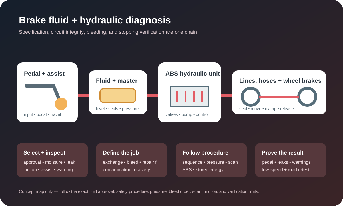
Treat changed pedal feel, red warnings, leakage, or lost braking as urgent
Stop safely and arrange recovery if the pedal suddenly sinks, becomes very soft or unusually hard, travels farther, braking force drops, the vehicle pulls severely, a red brake warning remains on after the parking brake is released, fluid leaks visibly, or smoke and burning odor appear at a wheel. Do not assume that adding fluid, pumping the pedal, or performing a flush makes the vehicle safe to drive.
Record the exact warning, pedal travel and firmness, whether pumping changes it, stopping behavior, recent brake or collision work, visible fluid, temperature, load, hill use, repeated stops, and whether the concern appears only after heat. A scheduled exchange and an active hydraulic integrity fault are different scopes. Loss of fluid or pressure must be located, repaired, and verified before routine maintenance is considered complete.
Identify the exact fluid chemistry, approval, and viscosity requirement
Confirm the VIN, model year, brake equipment, owner or service information, cap and reservoir labeling, and required fluid standard and approval. DOT 3, DOT 4, DOT 4 low-viscosity, DOT 5.1, silicone DOT 5, and mineral-oil systems are not chosen by color or a belief that the larger number is automatically better. Electronic stability and brake-by-wire systems can depend on specified low-temperature viscosity and material compatibility.
Do not mix incompatible chemistries or use a product solely because its dry boiling point looks higher. Use sealed or suitably fresh fluid that meets every stated requirement. Brake fluid damages paint and some materials; handle and clean spills according to the product and vehicle instructions. Record the product, approval, batch where useful, quantity, date and mileage so the next decision is based on traceable information.
Moisture, boiling point, viscosity, and corrosion describe different properties
Bosch describes common glycol-based brake fluid as hygroscopic: absorbed moisture lowers boiling point and can allow vapor formation under heat. Brembo distinguishes vapor lock in the hydraulic fluid from friction-material fade at the pad and rotor. Both can reduce braking yet need different corrections. Fluid also supports seal lubrication, corrosion control and valve response, so boiling point is not its only relevant property.
A moisture, conductivity or boiling-point tester provides useful evidence only when designed for the fluid, calibrated and used correctly. Reservoir color cannot quantify water, remaining inhibitors, viscosity or the fluid trapped at each wheel. A bright sample does not override the manufacturer interval, wrong-fluid history, an opened system or known contamination; a dark sample deserves investigation but does not automatically prove every hydraulic component is damaged.
A low reservoir level must be explained before it is topped off
As friction material wears, caliper or wheel-cylinder pistons can remain farther extended and reservoir level may fall within the designed range. Level can also drop from external leakage, internal hydraulic faults, incomplete prior filling, or a displaced reservoir or cap. Topping off without inspection can hide a leak and can overflow later when pistons are retracted during pad service.
Check the required level at the specified vehicle attitude and system state, then inspect the cap, diaphragm, reservoir, master cylinder and booster area, ABS hydraulic unit, rigid lines, flexible hoses, junctions, calipers, wheel cylinders, bleeders and connected hydraulic equipment. Identify fluid type by evidence; engine oil, coolant, washer fluid and hydraulic fluid can travel along structure and resemble a brake leak from a distance.
Exchange, bleeding, repair fill, and contamination recovery are separate jobs
A maintenance exchange replaces aged fluid according to schedule or supported condition. Bleeding removes air after a circuit has been opened or when diagnosis proves air is present. Filling accompanies component repair. Wrong-fluid or petroleum contamination can swell seals and affect multiple components, turning the work into a system-specific contamination recovery rather than a routine “flush.”
The estimate should state why the work is being performed, which circuits are included, whether the reservoir and clutch circuit share fluid, what method will be used, and how seized bleeders, corroded lines, leakage, contamination or failed hardware will be handled. A machine cannot repair seals, master-cylinder bypass, hose expansion, worn friction parts, sticking mechanisms, an ABS valve fault or incorrect mechanical adjustment.
Inspect friction, assist, and mechanical condition before blaming fluid
Pedal feel and stopping response also depend on pads or shoes, rotors or drums, caliper slides and pistons, wheel-cylinder movement, parking-brake adjustment, bearing condition, tires, vacuum or electric assist, pedal linkage and brake blending. Boiled fluid can create compressible vapor, while overheated friction can fade without hydraulic vapor. A hard pedal points toward a different path than a long soft pedal.
Inspect the complete foundation brake and assist system, warning status, heat evidence and recent work. Measure friction thickness and rotor or drum condition under the applicable limits. A hose can restrict internally without obvious external damage; a caliper can overheat the fluid by dragging; a rear adjustment fault can add travel. Correct the initiating condition rather than repeatedly exchanging fluid after every recurrence.
Choose the bleeding method and order from vehicle information
Systems may require pressure, vacuum, manual, gravity or scan-tool-assisted bleeding, sometimes in combination. Bosch emphasizes selecting fluid and pressure from vehicle specifications and notes that wheel order varies with application. The familiar rule to start at the wheel farthest from the master cylinder is not universal; circuit layout, ABS unit position and manufacturer procedure determine the sequence.
Never let the reservoir run dry, exceed equipment or system pressure, reuse extracted fluid, reverse-flow a system without approval, or improvise an order from another model. Keep dirt and moisture out, use clean dedicated equipment, protect paint and electronics, and fit tools securely. A blocked bleeder, rounded screw, corroded line or leaking adapter should stop the process for scope review rather than invite heat or force that creates a larger failure.
ABS, stability control, electronic boost, and brake-by-wire may need active procedures
Air can remain in an ABS or stability hydraulic unit after a low reservoir, component replacement, open circuit or incorrect bleed. Some vehicles require a scan tool to command valves, pumps or accumulators in a specified sequence; others prohibit unnecessary activation. Electronic boosters, integrated control units and brake-by-wire systems can store pressure or move components with the vehicle apparently off.
Read relevant modules and preserve codes before service. Follow power-state, accumulator discharge, high-voltage, electronic parking-brake and service-mode precautions for the exact vehicle. Confirm voltage support when required. A generic pedal-pumping sequence can produce misleading feel, move pistons unexpectedly or fail to clear a controlled passage. Document every commanded bleed or initialization step and its result.
Air, vapor, bypass, hose expansion, and mechanical travel feel different but overlap
A spongy pedal can support compressible air or vapor, but hose expansion, caliper flex, incorrect pad fit, rear shoe adjustment, bearing movement or structural deflection can contribute. A pedal that slowly sinks under steady force can involve master-cylinder bypass or external leakage, yet some electronically controlled systems change feel by design. Pumping that temporarily raises the pedal is evidence, not a complete diagnosis.
Compare behavior with engine or assist on and off only through the manufacturer test. Inspect for leakage under appropriate pressure, isolate circuits only with approved tools and limits, and observe wheel-end movement. Do not clamp reinforced hoses with damaging tools or assume a firm static pedal proves correct dynamic braking. The final diagnosis must connect the pedal pattern with verified hydraulic, assist and mechanical findings.
Regenerative braking does not eliminate hydraulic-fluid service
Hybrid and electric vehicles can use regenerative deceleration for part of normal braking, but still retain friction brakes and hydraulic controls for stopping, blending, stability, emergencies and low-speed operation. Reduced friction-brake use can change corrosion and wear patterns; it does not make fluid immune to time, moisture, heat, material compatibility or a manufacturer schedule.
The vehicle may include an electric booster, accumulator, integrated hydraulic unit or automatic brake functions that require disable and stored-energy procedures. High-voltage hazards and ordinary brake hydraulics are separate concerns that can coexist. Use trained personnel and exact information, and verify brake blending and warning status after service rather than judging the repair only from pedal feel while stationary.
Contamination requires source control and a defined component boundary
Petroleum products, power-steering fluid, mineral oil, coolant, washer fluid, cleaners, dirt or incompatible brake chemistry can damage seals or alter performance. Preserve a sample and record where the contamination was found, what was added, how much and how long the system operated. Do not pour unknown fluid into the waste container before evidence is captured.
The remedy depends on chemistry, exposure, component construction and manufacturer instruction. Simply pushing fresh fluid through may leave material in seals, hoses, master cylinder, hydraulic unit, calipers or wheel cylinders. Define which components can be cleaned, which must be replaced, how lines are handled and how the system will be proven clean. Prevent recurrence by correcting container, funnel, labeling or reservoir-identification errors.
Verification requires static pressure, low-speed checks, road behavior, and reinspection
After service, set level through the specified method, install the cap, clean spills, inspect every disturbed point under appropriate pressure, reinstall protective caps and wheels, and confirm a firm stable pedal through the correct static test. A pedal that remains spongy, sinks, changes after pumping or triggers a warning is not an acceptable result; diagnose retained air, leakage, bypass, hose, hydraulic-unit, mechanical or procedure faults.
Perform a controlled low-speed brake check before normal road testing, then evaluate consistent pedal, stopping response, pull, noise, vibration, ABS, stability, parking-brake and regenerative-braking status, including the original heat-related condition when safe. Recheck level and leaks after the test. Document the fluid, method, sequence, scan functions, measurements, repair findings and deferred items, clearly separating scheduled exchange from diagnosed repair.