
Timing-drive technical guide
A timing belt, tensioner, idlers, sprockets, seals, and related pump operate as one synchronized drive
A timing belt keeps crankshaft and camshaft motion synchronized on engines designed to use one. Its service decision is not based on belt appearance alone, and a tensioner is not an unrelated pulley. Exact engine identity, manufacturer time and mileage limits, documented history, drive layout, tensioning method, oil or coolant contamination, related rotating parts, required tools, engine damage risk, and post-installation verification define the complete job.
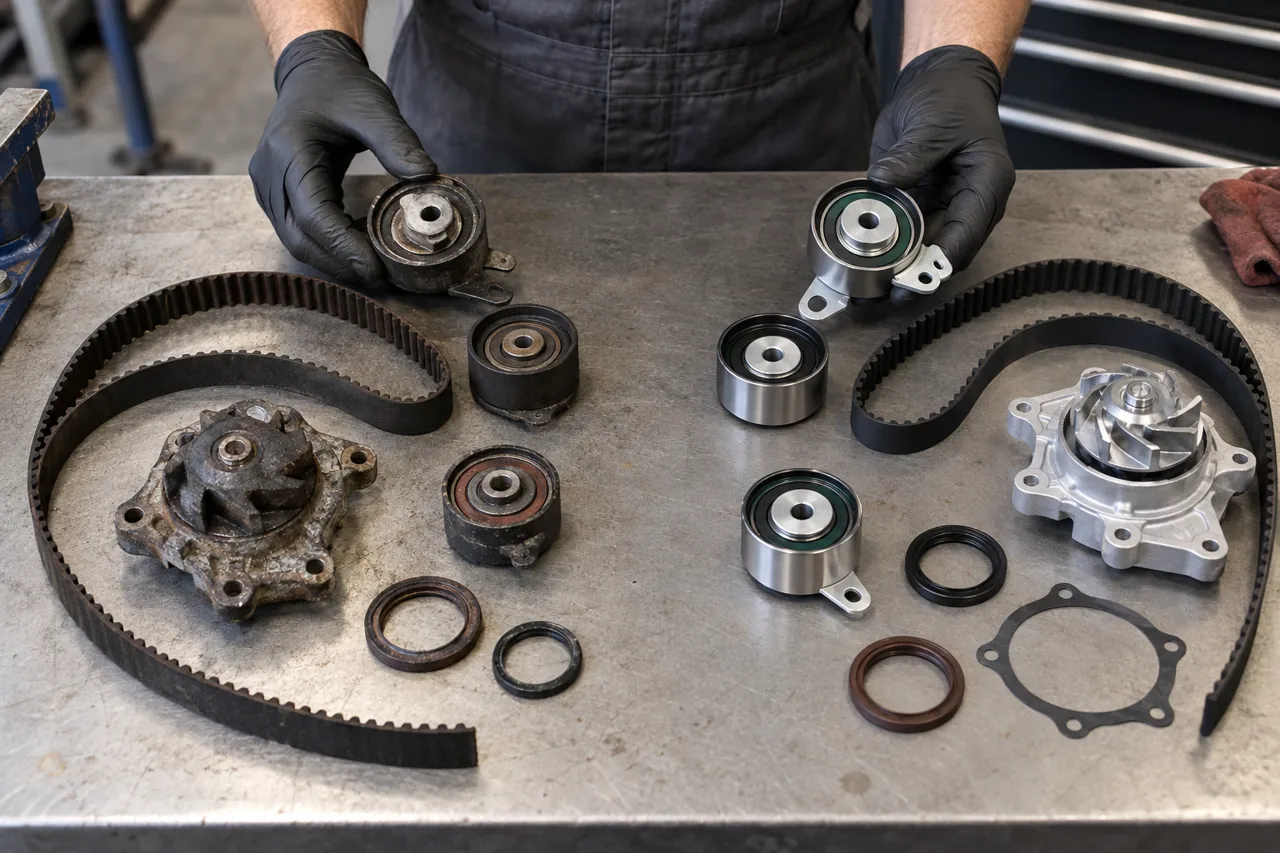
Confirm the exact engine and type of timing drive
Use the VIN, model year, production date, engine code, displacement, fuel type, market and installed configuration. A model name may include belt-, chain- and gear-driven engines across generations. Some engines use one belt for cam timing and another for a balance shaft or pump; some place a belt in oil; others use a belt only for a limited subsystem. An accessory serpentine belt is not a timing belt.
Identify dry or oil-immersed operation, number of camshafts, variable-timing units, balance shafts, high-pressure pump drive, mechanical or hydraulic tensioning, idlers, guide flanges, covers, seals and whether the water or oil pump is driven by the belt. These facts determine interval, material, oil compatibility, tool requirements and consequences. A generic video or parts catalog match cannot establish the correct procedure by itself.
Use manufacturer time and mileage limits plus documented history
Continental states that checking and replacement intervals are specified by the vehicle manufacturer and must be followed. Review both elapsed time and mileage, along with severe-use or market-specific provisions. A low-mileage belt can age, while a recently installed belt may still be at risk if the tensioner, pump, seals, hardware or installation were incomplete. Do not invent one universal interval for all European or imported vehicles.
Reliable history identifies date, mileage, exact kit or part numbers, tensioner and idler scope, water pump and coolant where applicable, seals, hardware and provider. A sticker without supporting detail, verbal claim, or clean-looking outer surface is weaker evidence. If history cannot be established, explain baseline replacement as a risk decision rather than claiming the remaining life can be measured visually.
Do not rely on a warning noise before scheduling service
Timing systems may show chirping, rubbing, rattle, hydraulic-tensioner leakage, tracking marks, edge wear, missing teeth, cracks, contamination, pulley roughness, cover damage or correlation codes. Those signs require prompt investigation, but some belts and bearings can fail without a dependable driver warning. Noise may also come from the accessory drive, variable-timing system, engine mount, oil-pressure condition or another rotating component.
Stop the engine after a sudden timing-area sound, immediate loss of power, belt debris, oil or coolant inside the cover, visibly displaced belt, correlation fault with poor running, or crank-no-start following an abnormal event. Do not repeatedly crank an engine with suspected shifted or broken timing. On an interference design, further rotation can add valve-to-piston contact; inspect and establish timing state first.
Read belt damage as evidence of a system cause
Dayco associates a clean break with handling or incorrect installation; a ragged break with foreign material, seizure, excessive tension or chemical exposure; side wear with misalignment; tooth loss with low tension or debris; and swelling with oil, coolant, fuel or solvent contamination. These patterns are not merely reasons to fit a new belt—they direct inspection toward the initiating condition.
Preserve the failed belt orientation, tooth and edge pattern, tensioner position, debris, cover marks, pulley surfaces and leakage before cleaning. Inspect sprocket compatibility, alignment, runout where specified, seized or rough bearings, guide orientation, foreign objects and mounting integrity. A replacement exposed to the same leaking seal, misaligned pulley, incorrect tension, damaged cover or failing bearing can fail quickly.
Tensioners control position and dynamic behavior—not just static tightness
Timing drives may use a locked eccentric or manual pulley, spring-loaded automatic tensioner, hydraulic actuator and pivoting arm, or an application-specific combination. Gates describes mechanical and hydraulic approaches that respond differently to belt and engine behavior. The installation may require indexing tabs, preload, a pin, slow actuator compression, a defined rotation sequence, temperature condition and indicator alignment.
Inspect bearing smoothness, pulley surface, arm and pivot, spring or hydraulic leakage, mounting points, indicator, damper, alignment and evidence of bottoming or impact. Excessive or insufficient tension can damage the belt, bearings and driven components. Do not infer correct tension by twisting the belt, pressing a span, or matching a generic deflection. Set and recheck the indicator exactly as specified after the prescribed engine rotations.
Idlers, sprockets, guides, covers, and hardware are active parts of reliability
An idler establishes belt path and can seize or tilt; a worn sprocket can damage tooth engagement; a mispositioned guide or cover can cut an edge; and a stretched or incorrect bolt can lose clamping. Inspect every rotating surface, flange, key, locating feature, bracket and cover. Gates application bulletins demonstrate that small clearances, fastener length, orientation and application updates can determine whether a belt tracks safely.
Define which tensioners, idlers, dampers, studs, bolts, nuts, washers, springs, seals and covers the kit includes. Some fasteners are torque-to-yield, staked or otherwise single use. Thread preparation, locking compound and torque-plus-angle instructions are not interchangeable. Reusing a questionable bearing or hardware to reduce the invoice may leave the new belt dependent on the oldest component in the system.
A timing-driven water pump creates shared access and shared risk
When the belt drives the water pump, bearing seizure, pulley play, leakage, cavitation damage or incorrect installation can directly harm the timing drive. Continental kits may include the belt, tensioning and guide pulleys, pump, seal and small hardware for that reason. Confirm the exact layout; a separately driven pump does not automatically belong in the same replacement scope.
Inspect the pump, mounting surface, drain or weep evidence, pulley and cooling-system condition. Define coolant specification, contamination or flush need, sealing method, torque, filling and bleeding. Do not spin a new pump dry contrary to instructions or use excess sealant. Timing verification and cooling verification remain separate deliverables: the engine must stay synchronized, and the cooling system must remain sealed, filled, bled and temperature stable.
Dry belts and oil-immersed belts have different contamination boundaries
A conventional dry timing belt must be protected from engine oil, coolant, fuel, cleaning chemicals and other liquids. Trace cam, crank, balance-shaft, pump and cover leakage and correct it before installation. Clean only with approved methods, replace contaminated components as directed, and ensure covers and breathers do not recreate the exposure.
An oil-immersed or wet belt is engineered for a specified oil environment, not for arbitrary lubricants. Incorrect oil approval, fuel dilution, service interval, sludge, chemical flush or material degradation can affect the belt and may spread debris into pickup screens, control valves or lubrication passages. Use the engine-specific inspection and remediation procedure; do not apply dry-belt rules or assume an oil change alone removes all consequences.
Exact reference positions and locking tools protect engine geometry
Establish crankshaft, camshaft, variable-timing actuator, balance-shaft and pump positions using the engine procedure and required holding or locking tools. Paint marks show only a relative position chosen by the installer and may preserve an already incorrect setup. They do not define top dead center, sprocket float, actuator preload, special rotation direction or the reference for a newly fitted engine.
Follow the belt routing, directional markings, slack placement, tensioner sequence, sprocket release or fastening, torque and angle values, and number and direction of hand rotations exactly. Never use the locking tool as a counterhold unless the procedure allows it, rotate against resistance, or use the starter for the first check. After controlled hand rotation, re-establish the reference and verify marks or tool fit plus tension indication.
A failed or shifted belt requires staged engine-damage assessment
Broken, stripped, jumped or severely displaced timing can leave valves and pistons out of phase. Interference risk depends on exact engine design and event. Compression, leak-down, borescope inspection, cam or valve movement, cylinder leakage location, oil and debris inspection, head removal or other controlled checks may be needed to identify bent valves, damaged guides, followers, camshafts, pistons or cylinder head.
Do not install a belt and crank the engine merely to see whether it starts. Define initial diagnosis, non-invasive checks, disassembly authorization, evidence for expanding the scope, repair versus replacement options and a stop point. The final plan should address why timing was lost—age, tension, seized component, contamination, hardware, installation, foreign object or consequential mechanical seizure—as well as the damage it caused.
Handling and installation can damage a belt before it runs
Continental warns that creasing can break internal glass-fiber tensile members even when exterior damage is subtle. Keep the belt and components protected until installation; do not kink, twist, sharply bend, lever, stretch, contaminate or force the belt over a flange. Confirm part number and tooth profile, then handle with clean hands and approved tools. Storage history and packaging condition matter for an aged or unknown part.
Clean mating surfaces without scratching or introducing debris, install seals and pumps correctly, confirm pulley freedom and alignment, and route the belt without trapping slack at the wrong span. Protect the work from loose fasteners, shop towels and cover fragments. Before closing the covers, perform an independent fastener and timing check so a missing torque step or retained locking pin is found before startup.
First start and heat-cycle verification complete the repair
Before startup, confirm free hand rotation, reference positions, tension indicator, removal of every lock and holding tool, fastener completion, cover clearance, accessory drive, connector and hose routing, oil and coolant levels and any required priming. Start without immediately raising engine speed; watch oil pressure, temperature, leaks, belt-area noise, tracking where observable and warning status. Shut down for any abnormal condition.
Review cam/crank correlation, misfire or timing data when meaningful, complete adaptations only when specified, and verify cooling-system bleed, heater and fan operation after pump work. Reinspect for oil, coolant, tracking and fastener concerns through cold and hot operation. The final record should state date, mileage, engine identity, belt and kit, tensioner and idlers, pump, seals, hardware, coolant, damage assessment, timing checks and the next manufacturer interval.