
Engine-management guide
Compare actual engine temperature with the sensor signal before replacement
An implausible coolant-temperature reading can come from the sensor, connector, wiring, reference or ground circuit, trapped air, low coolant, thermostat behavior, control module, or an actual cooling-system problem. Diagnosis begins with a cold-soak comparison and a controlled warm-up—not the code description alone.
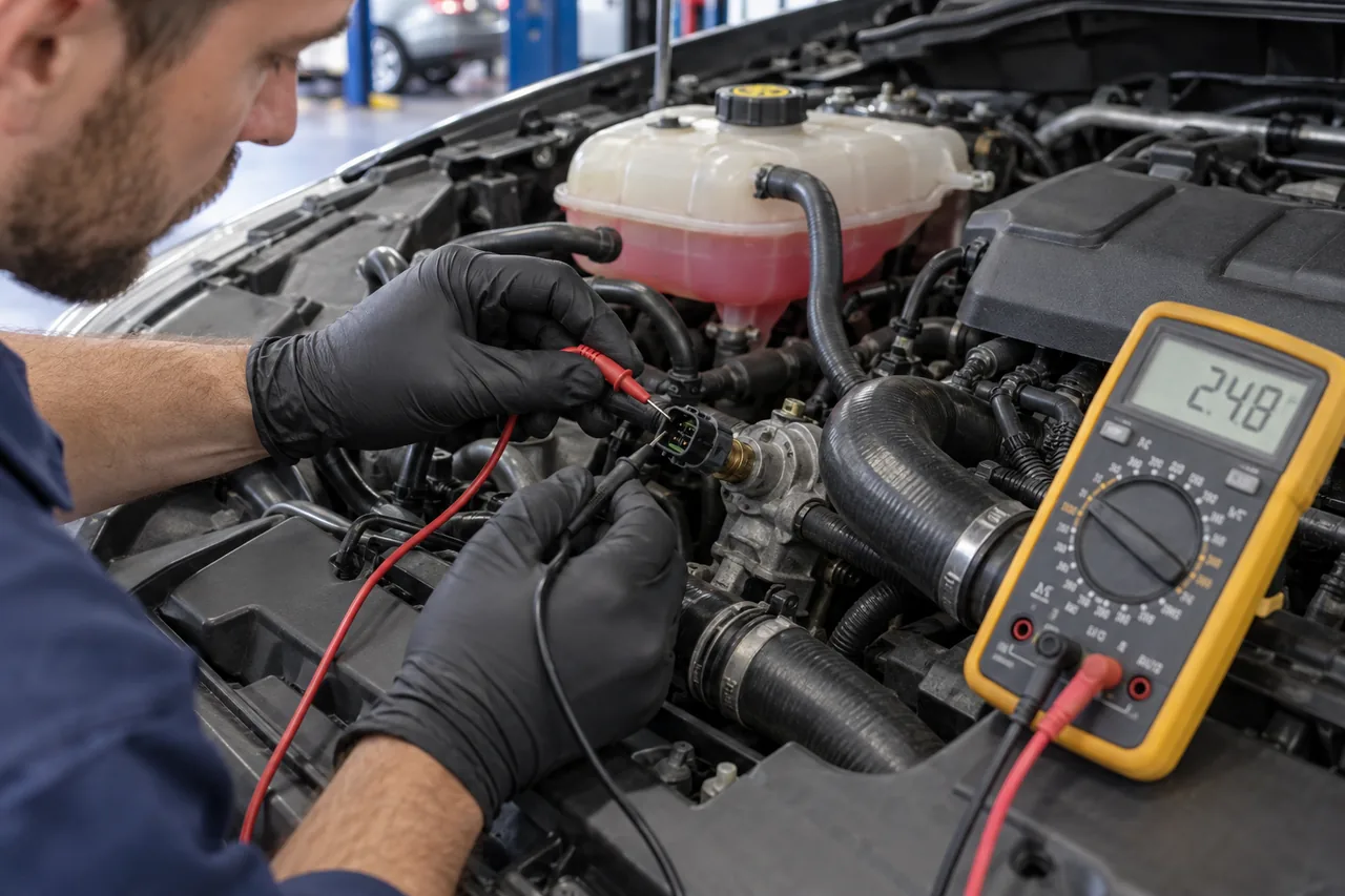
The short answer: diagnose the signal before replacing the sensor
Replace a coolant-temperature sensor only after actual engine temperature, scan data, coolant level, connector condition, and circuit behavior support that conclusion. A fixed extreme value, implausible cold reading, dropout, or signal that disagrees with independent temperature evidence can point toward the sensor or circuit; unstable temperature with low coolant, trapped air, thermostat trouble, or poor circulation calls for cooling-system diagnosis first.
Do not open a hot system or treat an overheating engine as a routine sensor job. The exact sensor location, seal, torque or retaining method, coolant specification, refill method, and bleed sequence are vehicle-specific.
What the coolant-temperature signal influences
The engine control system uses temperature information to understand warm-up and operating condition. Depending on the vehicle, that information can affect fueling, idle strategy, cooling-fan control, emissions monitors, dashboard indication, climate behavior, transmission decisions, and diagnostic checks. Some vehicles use one sensor signal in several modules; others use separate sensors or calculated values.
A failed or implausible signal can therefore create more than one symptom. It may produce a warning, difficult cold or hot starting, unusual fan operation, poor fuel control, weak heater diagnosis, or a gauge concern. Those symptoms are not unique to the sensor and must be compared with the engine’s actual temperature.
Begin with a true cold-soak comparison
Before the engine starts after sitting long enough to reach ambient temperature, coolant-temperature data should be compared with intake-air temperature, outside temperature, and other available temperature values. They need not be numerically identical, but a large unexplained difference can provide a useful direction before the engine adds heat.
A believable cold reading does not prove the circuit is healthy through its full range. Watch the signal during a controlled warm-up for smooth, plausible change. Sudden jumps, dropouts, a fixed extreme value, or disagreement with an independent temperature measurement can indicate a sensor, connector, wiring, air pocket, or circulation issue.
Check coolant level and system condition first
A temperature sensor must be exposed to the medium and conditions the design expects. Low coolant, trapped air, poor circulation, thermostat behavior, leakage, combustion gas, or a recent incorrect bleeding procedure can produce misleading or unstable readings. Resolve an overheating or rapid coolant-loss condition before treating it as a simple sensor job.
Never open a hot pressurized cooling system. Steam and hot coolant can cause severe injury, and releasing pressure can intensify boiling. If the engine is overheating, the gauge rises rapidly, cabin heat disappears, or coolant escapes, stop safely and allow qualified inspection rather than continuing a diagnostic drive.
Separate the sensor from its circuit
Service information may specify resistance, voltage, reference, return, or plausibility checks at defined temperatures. The correct values and test points vary. Back-probing or disconnecting a circuit without the proper method can spread terminals or create a new fault, so connector inspection and approved test leads matter.
A scan reading that changes when the harness moves can suggest an intermittent connection. Corrosion, coolant intrusion, oil contamination, heat damage, pin tension, a rubbed wire, poor ground, or a reference circuit shared with another sensor can mimic sensor failure. Testing should show whether the input is wrong at the sensor, along the circuit, or inside the receiving module.
Plan replacement around coolant loss and access
Some sensors thread into a housing; others use a retaining clip and seal. Location can require removing intake, air-cleaner, battery, hose, or other components. The estimate should identify the sensor, seal or clip, coolant needed for lost volume, access operations, and any damaged connector or housing discovered during inspection.
Use the exact application and procedure. An incorrect seal, damaged sealing surface, over-tightening, reused clip, or connector forced onto the wrong part can create a leak or unreliable signal. If significant coolant is drained, confirm the required coolant specification and whether a vacuum fill or model-specific bleed procedure is necessary.
A bounded replacement workflow
For the exact vehicle, first confirm the component identity and service procedure, allow the engine to cool, establish the required coolant level or draining method, disconnect power only when the procedure requires it, protect connectors and openings, and replace the specified seal, clip, or threaded sensor without forcing the housing. Restore every component removed for access and refill only with the correct coolant and method.
This sequence is deliberately not a universal step-by-step repair. Some systems require vacuum filling, electric-pump activation, scan-tool functions, special venting, or a cold-level check after a complete heat cycle. If those instructions and safe equipment are unavailable, professional service is the appropriate next action.
Worked scenario: a cold reading that is already hot
Consider a vehicle left overnight where ambient and intake-air readings are near one another but the coolant value reports a much hotter engine before startup. Because the engine has not produced heat, the discrepancy supports checking the sensor circuit, connector contamination, wiring, reference or ground, and the sensor itself before investigating thermostat opening or fan performance.
If moving the harness makes the reading jump, circuit integrity becomes more important than replacing the sensor immediately. If the connector and wiring pass and a specified test confirms the sensor is biased, replacement is supported. Repeating the cold comparison after repair provides stronger verification than clearing the code and watching the dashboard light.
Bleeding and leak checks are part of the job
Air left in the cooling system can interrupt heater operation, distort temperature behavior, and contribute to overheating. Bleeding may require designated vents, heater settings, scan-tool pump activation, vacuum filling, or a specific warm-up and cool-down process. A generic “top off and drive” instruction is not safe for every vehicle.
Inspect the sensor seal and every connection disturbed during access under the appropriate pressure and temperature conditions. Recheck level only using the vehicle procedure and when safe. A dry sensor area immediately after installation does not replace a complete heat cycle and cold-level confirmation.
Verify signal plausibility and cooling-system operation
After repair, repeat the cold comparison when practical, then watch a smooth warm-up. Confirm that the measured engine temperature and scan value agree plausibly, the thermostat and fan behavior make sense, the heater operates, and the system remains stable without leakage or unexpected level loss.
Clear faults only after recording them, then confirm that relevant monitors and messages behave correctly. If the value remains implausible, return to the circuit, coolant level, air, and actual temperature rather than installing another sensor. Verification must explain both the electrical signal and the physical cooling condition.