
Vacuum and brake-assist technical guide
Vacuum-pump replacement starts with proving the complete brake-assist system
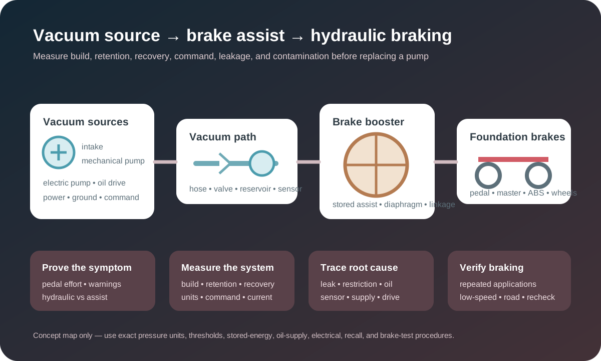
A hard pedal, brake-assist warning, long pump run, hissing, oil leak, vacuum code, or low measured vacuum does not automatically identify a failed pump. The system may depend on intake-manifold vacuum, a mechanically driven pump, an electric pump, a check valve, reservoir, pressure sensor, hoses, brake booster, electrical control, lubrication supply, or a combination. A safe diagnosis separates assist from foundation braking, measures vacuum build and retention under the correct conditions, locates leakage or contamination, and verifies repeated brake applications after repair.
Treat sudden hard-pedal effort or reduced stopping performance as urgent
Slow and stop safely if the brake pedal becomes suddenly hard, assist drops intermittently, stopping distance increases, a red brake warning appears, the vehicle requires much more pedal force, or a “service brake assist” message accompanies changed braking. Do not continue because the foundation brakes may still function; NHTSA recall material documents that reduced vacuum assist can increase pedal effort and stopping distance.
Use the parking brake only as the vehicle instructions and traffic conditions permit. Do not repeatedly test the failure in traffic, switch the engine off while moving, or assume pumping the pedal will restore assist. Arrange recovery when normal braking cannot be confirmed. A hard pedal differs from a soft or sinking pedal, but several faults can coexist, so the complete braking system still requires inspection.
Identify the vacuum source, control strategy, and connected consumers
Some gasoline engines create booster vacuum in the intake manifold; turbocharged, downsized, diesel, hybrid, stop/start and other applications may use a camshaft-, crankshaft-, belt- or electrically driven pump. A vehicle can use a mechanical primary pump plus electric support. The system may also include a reservoir, sensor, check valves and vacuum consumers for mounts, emissions, turbo controls or other actuators.
Confirm VIN, engine, production variation, brake and powertrain equipment, routing and diagrams. Identify whether a pressure sensor directly measures the booster line or whether control software estimates need from engine speed, load, throttle and brake input. HELLA describes both sensor-regulated and calculated strategies. A generic pump video cannot establish source, threshold, hose path, electrical logic or safe test procedure.
Separate loss of assist from hydraulic, friction, and mechanical brake faults
Vacuum assist reduces the force a driver must apply; it does not generate wheel braking independently of the master cylinder, hydraulic circuits, ABS unit and friction brakes. Loss of assist commonly raises pedal effort, while air or leakage may create long or soft travel. Caliper seizure, friction fade, contaminated pads, master-cylinder bypass, hose restriction and tire conditions can change stopping behavior without a vacuum-pump fault.
Record pedal effort and travel, whether engine start changes pedal position under the prescribed check, warning lights, vacuum data, hydraulic leakage, recent brake work, heat, pull and friction condition. Do not condemn a pump from a hard pedal alone, and do not treat an acceptable vacuum value as proof that the booster linkage, diaphragm, master cylinder and wheel brakes are healthy.
Inspect hoses, fittings, check valves, reservoirs, and booster before the pump
Trace every vacuum hose from source to booster and reservoir, looking for cracks, collapse, oil softening, heat damage, abrasion, loose connectors, damaged O-rings, restricted fittings, incorrect routing and previous repairs. Inspect the booster grommet, shell, master-cylinder interface and corrosion. A hose can seal at rest and open when the powertrain moves or when temperature changes.
Check valves should permit flow and retain vacuum in the specified direction; reservoirs add capacity but can leak at seams or fittings. Isolate sections only with approved equipment and without damaging reinforced hose. Compare source vacuum, booster-line vacuum, build time and retained vacuum rather than assuming a visible hose is airtight. Hissing locates an area, not necessarily the exact failed component.
Measure vacuum or absolute pressure with units and operating conditions stated
Vacuum may be displayed as pressure below atmosphere, absolute pressure, inches of mercury, kilopascals, millibar or another unit. Record ambient pressure, units, engine or pump state, temperature, speed and brake applications. A number without its reference and condition can invert the conclusion. Use rated gauges, scan data and specified test ports without introducing a leak or contaminating the system.
Measure initial level, source build rate, booster build rate, cut-in and cut-out where controlled, retention after shutdown, and recovery after repeated pedal applications according to service information. Low vacuum can reflect inadequate source output, leakage, restriction, bad check valve, reservoir fault, booster leak, sensor bias, incorrect control or altitude. One idle reading does not prove recovery under stop/start or repeated braking.
Mechanical pumps need drive, lubrication, sealing, and engine-condition checks
An engine-driven pump can use a camshaft, crankshaft, chain, gear or belt interface and may rely on engine oil for lubrication and sealing. Inspect drive tangs, lobes, followers, splines, couplings, mounting faces, gaskets, oil supply and return, pump wear and nearby engine condition. Noise or failure can originate in the drive or oil path rather than the pump body alone.
Pierburg/Motorservice advises checking lubrication supply before installing a replacement on affected applications. Low oil level or pressure, restricted passages, incorrect assembly, debris, sludge or sealant can destroy the new pump. Conversely, a pump leak can lower engine-oil level or contaminate the vacuum circuit. Confirm the root cause and circulation boundary before deciding that one replacement completes the repair.
Electric pumps require command, power, ground, current, and pressure response
HELLA notes that an electric vacuum-pump failure can involve voltage supply, external damage, motor failure or contaminated or damaged lines. Read relevant engine, brake and body modules before clearing codes. Record pump command, booster pressure, brake-switch or pedal data, engine state, start/stop status, temperature and voltage under the condition that triggers operation.
Test fuses, relay or solid-state driver, battery supply and ground under load, connector condition, harness routing, command and feedback. An unloaded 12-volt reading can hide excessive resistance. Compare current and sound with actual vacuum build: a commanded silent pump may have an electrical or motor fault; a running pump that cannot build may face a leak, restriction, sensor error or mechanical pump fault; excessive run time can overheat the unit while the true leak remains.
Pressure-sensor data must be checked for plausibility and circuit integrity
A brake-booster pressure sensor can participate in electric-pump control and diagnostics. A code can describe signal range, plausibility, circuit high or low, or system performance; it does not prove the sensor is the only failed part. Compare key-on engine-off data with ambient pressure using the correct interpretation, then observe a smooth response as vacuum builds and decays.
Inspect reference supply, ground, signal, terminals, oil or water intrusion, hose connection and the sensor’s exposure to actual system pressure. Compare scan data with a trusted gauge where the procedure supports it. A biased sensor can run a good pump unnecessarily or fail to request support, while a real leak can make accurate data look abnormal. Replace only after the circuit and pneumatic relationship agree.
Oil migration or fluid contamination can expand the repair far beyond the pump
Engine oil can enter a vacuum line through a failed pump or check-valve arrangement and reach the booster. NHTSA investigation material documents an application where oil exposure damaged booster diaphragms and the corrective scope could include the pump, tube, booster and master cylinder. This is application-specific evidence, not a universal replacement list, but it illustrates why contamination must be traced.
Record the fluid type, location, amount and direction of migration before cleaning. Inspect every affected hose, valve, reservoir, sensor and booster under exact service or campaign guidance. Do not wash oil through the booster or assume replacing the pump removes absorbed material. Also distinguish brake fluid leaking from the master cylinder into the booster from engine oil arriving through the vacuum line; the source changes the repair boundary.
Check recalls, campaigns, software, and exact configuration before parts replacement
Vacuum-assist complaints have produced safety recalls involving hardware, contamination and control calibration. Check the exact VIN through authoritative recall systems rather than assuming a model-year list applies. Recall remedy and ordinary diagnosis are separate: an open campaign follows its prescribed process, while a vehicle outside the population still requires evidence-based testing.
Software can change pump control or fallback brake-assist behavior, but programming should not mask a physical leak or damaged component. Verify calibration level and applicable service information after mechanical and electrical findings are understood. Document whether the vehicle has modified brake, engine, intake or vacuum equipment, because altered routing or calibration can change available vacuum and monitoring behavior.
Replacement scope includes seals, lines, valves, oil supply, wiring, and setup
Define whether the work includes a mechanical or electric pump, gasket or seal, drive component, oil passage correction, hose assembly, check valve, reservoir, pressure sensor, booster, master cylinder inspection, electrical connector, relay, software or other contaminated components—and state why. Related parts should follow evidence and application instructions, not proximity alone.
Depress stored vacuum and other brake energy through the specified method, isolate electrical or high-voltage systems where applicable, keep openings clean, and use correct fasteners and torque. Prime or lubricate a mechanical pump only as directed, align drive features without force, route lines against heat and abrasion, and confirm check-valve direction. Electric pumps mounted below the vehicle also require water, debris and bracket protection.
Verification must test repeated applications, retention, warnings, and stopping
After repair, inspect every pneumatic, oil and electrical connection, then measure vacuum build, cut-in and cut-out where controlled, recovery after repeated pedal applications, and retention after shutdown under the vehicle procedure. Confirm plausible sensor data, expected pump command and current, no excessive run time, no oil or air leakage, normal engine-oil level and pressure, and no unexplained brake or powertrain codes.
Perform a controlled static pedal check and low-speed stopping check before a normal road test. Recreate cold start, hot idle, stop/start, altitude or repeated-brake conditions when safely possible. Confirm consistent assist, pedal effort, stopping response, ABS and stability status, and no warning recurrence. Reinspect after a heat cycle and document measurements, units, operating states, recall check, parts, contamination scope and any remaining hydraulic or friction findings.