
Electrical diagnosis
Seattle-area auto electrical repair starts with a loaded circuit test
A dead battery, slow crank, warning lamp, intermittent no-start, or repeated low-voltage fault in SeaTac or Seattle does not identify a single failed part. The battery, alternator, starter, cables, grounds, control strategy, wiring, and vehicle loads must be evaluated under the condition that produces the symptom.
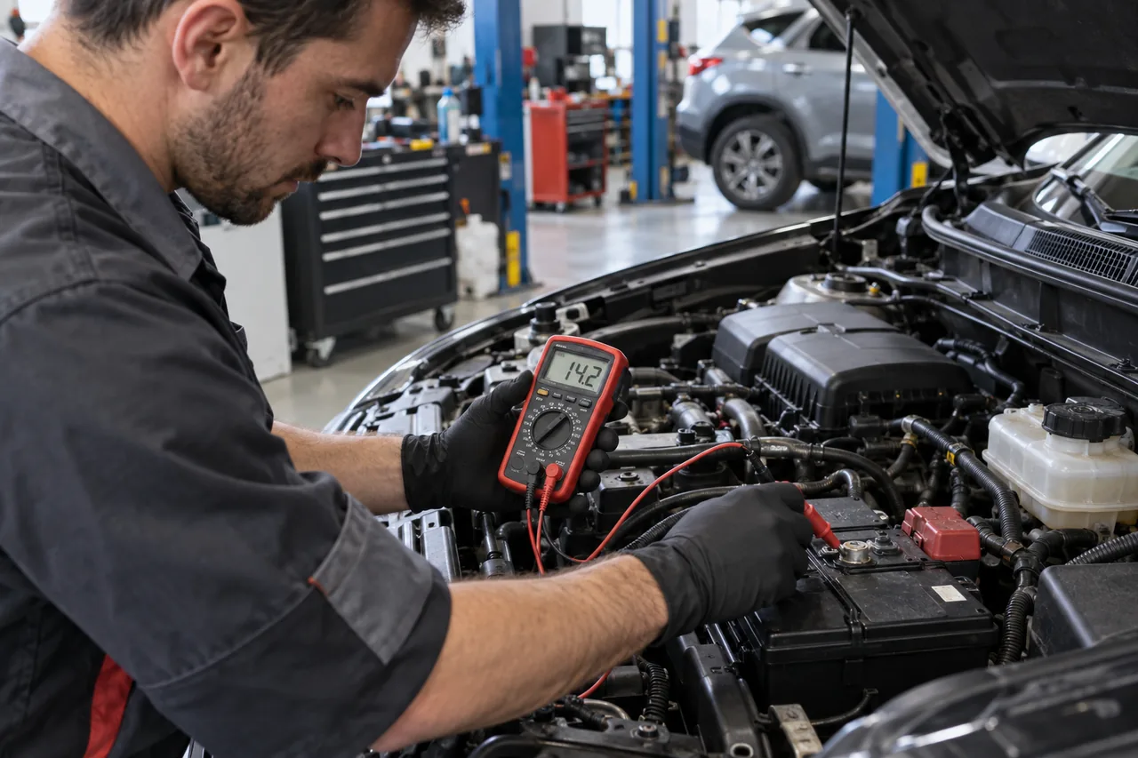
Quick decision: identify the electrical failure mode first
No power, no crank, slow crank, normal crank with no start, a battery that goes flat while parked, and a charging warning while driving are different problems. Record which loads still operate, whether a jump changes the symptom, how long the vehicle sat, ambient conditions, recent battery or accessory work, and every warning message before choosing a battery, starter, or alternator.
A voltage number without load and context is not enough. The useful first test may be battery capacity, starter current and voltage drop, charging output and command, key-off draw after modules sleep, or circuit integrity at the failing component.
Define the exact failure mode before testing
“It would not start” can mean no dashboard power, normal lights with no crank, a single click, rapid clicking, slow cranking, normal cranking without combustion, or an engine that started and then stalled. Each pattern changes the likely circuit and test sequence. Record ambient temperature, how long the vehicle sat, recent short trips, warning messages, accessory behavior, jump-start results, and whether the symptom is intermittent.
A charging warning commonly refers to charging-system performance, not proof that the battery itself failed. Stop safely if the warning appears with overheating, heavy steering, belt noise, smoke, burning odor, repeated electrical shutdown, or rapidly dimming systems. Continued driving on stored battery energy can end without warning, while a damaged belt may also affect other engine systems.
Battery state of charge and battery health are different
Open-circuit voltage can help describe state of charge after an appropriate rest period, but voltage alone does not prove that a battery can deliver current during starting. A discharged but otherwise serviceable battery and a charged battery with poor capacity require different conclusions. Identify battery technology, rating, age when known, temperature, and vehicle energy-management requirements before selecting a test and interpreting its result.
A complete record can include measured voltage, tester method, entered battery rating and standard, state-of-charge or conductance result, and voltage behavior during crank. Bosch equipment documentation distinguishes testing of batteries from extended starting and charging-system tests, illustrating why one number should not stand in for the whole system. Recharge and retest when the chosen procedure requires it rather than condemning a discharged unit automatically.
Inspect connections and measure voltage drop under load
Corrosion, looseness, damaged terminals, hidden cable deterioration, poor engine or body grounds, fuse links, and previous accessory wiring can create resistance that appears only when current flows. A connection can show battery voltage with no load and still fail during cranking or charging. Inspect physical condition, then measure voltage drop on the relevant positive and ground paths while the circuit is operating.
Do not clean or disconnect blindly before capturing the symptom and stored information. Battery removal can erase settings or diagnostic context, and some vehicles require support power, registration, adaptation, or initialization after replacement. Follow vehicle-specific safety and service procedures. Never treat high-voltage hybrid or electric-vehicle components as an extension of ordinary 12-volt testing; those systems require trained personnel and dedicated isolation procedures.
Worked scenario: a slow crank with a battery that tests charged
Consider a vehicle that cranks slowly even though open-circuit voltage and state of charge appear acceptable. Measuring voltage at the battery alone cannot show whether current is being lost through a corroded positive connection, weak ground path, starter fault, mechanical drag, or a battery that lacks capacity under load. Cranking current, battery voltage under load, and voltage drop across both cable paths separate those possibilities.
If excessive drop appears across a ground connection and cleaning or repairing that connection restores cranking speed, replacing the battery or starter would have been unnecessary. The editorial judgment is that measurements taken while the circuit performs its real job are more useful than unloaded voltage or a parts-store label.
A no-crank diagnosis follows command, control, and current
Confirm that the correct start request reaches the system and that interlocks such as selector position, clutch input, immobilizer authorization, brake input, network communication, and module power are behaving as designed. Then evaluate starter control voltage, available voltage at the motor, ground path, current draw, engine mechanical freedom, and the sound or speed of engagement.
DENSO technical material notes that a starter which passes a bench performance test directs attention back to the vehicle starting circuit and other electrical circuits. Conversely, an out-of-spec starter result must still be considered with cable condition and engine load so a new unit is not installed into the cause of the original failure. Clicking or silence is a clue, not a component verdict.
Charging voltage is controlled and condition-dependent
Modern charging systems may vary output with battery state, temperature, electrical demand, braking or coasting strategy, and module commands. A single idle-voltage rule can misclassify normal operation or miss a fault. Use service information and test the system under relevant loads while reviewing requested output, actual voltage, current where appropriate, warning-lamp behavior, belt drive, connections, and communication faults.
DENSO’s alternator guidance begins with the observed symptom and lists battery condition, terminal connections, fuses, wiring, added electrical load, and control circuits among possible causes of charging complaints. Excessive AC ripple, noise, overheating, intermittent output, or a warning lamp can require different checks. Explain whether the evidence supports the alternator itself or a surrounding circuit.
Repeated discharge requires a sleep-state test plan
A battery that goes flat after parking may be weak, insufficiently recharged by the drive pattern, affected by a charging fault, or drained by a load that remains active. Record how long the vehicle sits and whether the problem follows a door, key, charger, accessory, software event, weather condition, or recent work. Verify battery condition before interpreting an off-key current measurement.
Many modules remain awake for a designed period and can wake when the vehicle is unlocked, a key is nearby, a network message occurs, or a test connection changes. A valid parasitic-draw test controls those variables, waits for the documented sleep process, and isolates the circuit without repeatedly waking it. Pulling fuses at random can alter the evidence and create new faults.
Low voltage can produce secondary warnings and communication codes
During cranking or unstable charging, modules may record undervoltage, lost communication, implausible sensor signals, restraint, steering, transmission, or chassis warnings. Those records should be saved with timestamps and voltage context before clearing. Repairing the primary supply problem may resolve secondary codes, but every safety-related warning still needs the verification specified for that system.
Do not replace multiple modules because they all reported faults during the same voltage event. Establish stable power and grounds, confirm network integrity, then reassess which codes return under normal conditions. If a fault remains isolated to one circuit, continue with its wiring diagram and component tests rather than assuming the battery was the only problem.
Replacement and verification must match the vehicle
If battery replacement is supported, confirm physical size, terminal orientation, capacity and rating, battery technology, venting, hold-down, energy-management registration, and required resets. If a starter or alternator is supported, define access, belt or tensioner condition, one-time-use hardware, cable repair, control diagnosis, and any programming or adaptation. The estimate should distinguish the failed component from work needed to correct its cause.
After repair, repeat the original cold or hot start condition, starting-system test, charging test under appropriate loads, and any sleep-current check. Confirm secure connections, normal warning status, restored settings or adaptations, and absence of new codes. A successful result explains the pre-repair failure, the evidence supporting the chosen scope, and the measurements showing that the connected system now works correctly.