
Steering-assist technical guide
Power-steering fluid and pump decisions begin by identifying the system
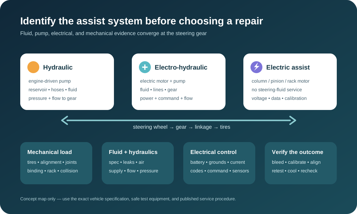
Heavy steering, intermittent assist, a warning message, fluid loss, whining, foaming, or poor return-to-center does not automatically identify a bad pump or a need for a flush. The vehicle may use a belt-driven hydraulic pump, an electric hydraulic pump, or fully electric assist with no steering fluid. Tires, alignment, mechanical joints, voltage, sensors, software, hoses, the steering gear, and previous repairs can create overlapping symptoms. Diagnosis must establish the architecture, reproduce the concern, and test the complete steering path before choosing fluid service or component replacement.
Stop when steering control or a high-pressure leak is unsafe
Slow smoothly and stop in a safe location if steering effort changes suddenly, assist drops in and out, the wheel binds, a red steering warning appears, smoke or fluid reaches a hot exhaust surface, a hose sprays, a belt or pulley fails, or the vehicle cannot be directed predictably. Some vehicles retain manual steering after assist loss, but effort can rise sharply—especially at low speed—and the exact behavior cannot be assumed from another model.
Do not place hands near a suspected high-pressure leak, search for it by touch, open a hot reservoir, or work beneath an unsupported vehicle. Hydraulic fluid can penetrate skin and can ignite on hot components. Electric-assist systems can move or remain energized under conditions defined by the vehicle. Arrange recovery when control is uncertain, leakage is rapid, the drive belt also operates critical accessories, or the correct isolation procedure is unavailable.
Identify hydraulic, electro-hydraulic, or fully electric assist first
A conventional hydraulic system generally uses an engine-driven pump, reservoir, pressure and return lines, and a hydraulic steering gear or rack. Electro-hydraulic power steering uses fluid and a hydraulic gear but drives the pump with an electric motor. Electric power steering applies assist through an electric motor at the column, pinion, rack, or another mechanism and normally has no power-steering reservoir, pump, or fluid service.
Confirm the exact vehicle identification, engine and option codes, underhood label, service information, visible components, and module inventory. Do not pour fluid into a similarly shaped reservoir or recommend a flush because the dashboard says “power steering.” Some central hydraulic systems share an approved fluid with suspension, stability, rear-steering, roof, or other functions. Misidentifying the architecture can damage unrelated systems and prevents a valid test plan.
Reproduce the symptom and separate assist from mechanical load
Record whether the concern occurs cold, hot, at idle, with engine speed, during parking, at road speed, near full lock, after rain, over bumps, during lane-assistance intervention, or after battery, alignment, collision, tire, suspension, rack, or engine work. Note warning messages, sounds, steering effort in both directions, return-to-center, pull, kickback, vibration, wheel position, and whether restarting temporarily changes the behavior.
Low tire pressure, mismatched tires, alignment, a seized joint, strut mount, ball joint, tie rod, steering shaft, wheel bearing, brake drag, damaged rack, subframe movement, collision damage, or excessive caster can imitate weak assist. With the vehicle supported and isolated only as the procedure permits, evaluate the mechanical path rather than forcing the wheel. Assist diagnosis is incomplete until abnormal mechanical resistance and tire load are considered.
Use the exact fluid specification—not color or a generic label
Hydraulic steering systems may require a dedicated power-steering fluid, a specified automatic-transmission fluid, or a central hydraulic fluid approved to a particular manufacturer standard. Pentosin’s application information distinguishes several formulations used in modern hydraulic systems. Similar color does not prove interchangeability, and a bottle labeled “universal” does not override the owner or service specification.
Record the specification already required, not just viscosity or color. Mixing incompatible fluids can change seal behavior, lubrication, low-temperature response, foaming, noise, and material life. An unknown or incorrect fill requires a reasoned remediation plan; repeated dilution may not remove material trapped in a gear, cooler, reservoir filter, or shared circuit. Never add brake fluid, engine oil, coolant, or an unverified stop-leak additive to a steering reservoir.
Fluid level and condition are evidence, not stand-alone diagnoses
Read level at the specified temperature, engine state, cap or dipstick orientation, and wheel position. Some reservoirs use different hot and cold marks; some are difficult to see or contain a nonserviceable filter. A falling level means fluid left the system or was displaced during incomplete filling. Topping off may restore assist temporarily but does not repair a leak or explain why air entered.
Inspect color, clarity, odor, foam, suspended material, water evidence, rubber debris, metal, mixed fluid, and reservoir-screen restriction while recognizing that appearance alone cannot prove additive condition. Dark fluid may reflect age, heat, hose material, rack or pump wear, or previous mixing. Bright fluid can still be wrong. Preserve a sample when contamination affects the repair scope, and trace whether debris originated upstream or circulated through the entire system.
Trace leaks from the highest clean evidence point
Clean only after documenting wetness and follow the circuit from reservoir and feed hose through pump, pressure hose, cooler where fitted, steering gear or rack, return line, clamps, seals, and connections. Look for abrasion, sweating versus active leakage, cracked reservoirs, loose clamps, distorted fittings, corrosion, heat damage, hose movement, pulley sling patterns, and fluid collected inside rack bellows. Fluid can travel along a hose, crossmember, shield, or airflow path before dripping.
Use an approved dye or controlled inspection method when needed, never an improvised pressure that exceeds system limits. A leaking shaft seal does not reveal whether pulley misalignment, belt load, contaminated fluid, restriction, or excessive pressure contributed. A wet rack boot can support an internal rack-seal leak but should be distinguished from water, grease, engine oil, or fluid migrating from above. Recheck under the temperature and steering load that produced the leak.
Noise can come from air, restriction, drive parts, pressure, or the pump
Whine, growl, chatter, squeal, hiss, and clunk have different paths. Aerated fluid can make a pump noisy and assist erratic; air may enter through a low level, suction-side leak, loose connection, damaged O-ring, restricted reservoir filter, or incomplete bleeding without producing an obvious outward leak. Belt slip, tensioner or pulley faults, engine vibration, hose contact, steering stops, gear valves, or mechanical joints can sound like pump failure.
Observe fluid behavior safely, inspect supply and return restrictions, check belt condition and alignment where applicable, and compare noise with pressure demand, temperature, engine or electric-pump speed, and steering direction. Holding against full lock can generate maximum pressure and heat; do not use it beyond the exact test allowance. A quiet replacement pump can be damaged quickly if the suction leak, dirty reservoir, wrong fluid, or overloaded steering gear remains.
Pump testing connects supply, command, flow, pressure, and load
For an engine-driven pump, inspect mounting, pulley condition and runout, drive-belt path and tension, reservoir supply, inlet sealing, hose restriction, and evidence of shaft leakage before hydraulic testing. Pressure and flow gauges require rated equipment, correct adapters, safe hose routing, temperature awareness, and the vehicle-specific test sequence. A pressure number without flow and steering-load context can misidentify the pump or gear.
Electro-hydraulic pumps also require battery and charging condition, high-current supply, grounds, fuses, relays or controllers, network communication, commands, feedback, temperature, and current under load. Voltage that looks normal with the pump off can collapse when current rises. Scan codes identify monitored conditions, not automatically a failed assembly. Compare command with actual operation and isolate wiring or supply faults before replacing an expensive pump module.
A flush or exchange needs a defined reason and controlled method
Fluid service may be appropriate for a published maintenance requirement, incorrect or degraded fluid, contamination, component failure debris, or as part of a supported repair. A reservoir extraction changes only part of the fluid. A line exchange can replace more but can run the pump dry, introduce air, spill fluid, or move contamination if performed without the correct route and supply. Machine flushing, solvents, compressed air, or additives are not universally approved.
Define the target specification, reason, amount, circuit boundaries, reservoir or filter service, waste handling, and completion criterion before authorization. If metal or seal debris circulated, decide which hoses, cooler, reservoir, pump, or gear can be cleaned reliably and which require replacement under the applicable procedure. A fluid color change alone is not proof that hidden contamination is gone, and a flush cannot repair worn bearings, damaged valves, leaking seals, or an electrical EPS fault.
Replacement scope must correct the cause and protect the new component
A pump repair plan can include the pump or motor assembly, reservoir and filter, inlet and pressure seals, hoses, cooler, pulley transfer, belt and tensioner findings, electrical connector repair, specified fluid, contaminated-circuit remediation, one-time hardware, and the steering gear condition. Explain which items are confirmed faults and which are preventive choices rather than presenting every nearby part as failed.
Compare ports, pressure and flow rating, rotation, pulley offset, connector, control software, and vehicle application before installation. Keep openings clean and capped, lubricate seals only as directed, use suitable line wrenches and specified torque, support hoses against twist, and align pulleys. ZF’s pump guidance emphasizes maintaining fluid during bleeding; never operate a new pump dry. On EPS racks or columns, follow high-voltage, restraint, steering-lock, and module programming precautions that apply.
Bleeding, calibration, alignment, and a loaded retest finish the repair
Fill with the exact fluid and perform the model-specific bleed sequence. The procedure may involve engine-off wheel movement, vacuum filling, electric-pump activation, staged engine operation, raised or loaded wheels, temperature limits, and repeated level checks. Watch for persistent bubbles, foam, noise, unstable level, leakage, or assist changes. More cycling is not a cure for an unresolved suction leak, restriction, wrong fluid, or damaged component.
After hydraulic, rack, column, battery, alignment, or suspension work, verify steering angle and torque data, end stops, centering, wheel alignment, driver-assistance calibration, module coding, and learned values as required. Road-test safely from parking speed through the original condition, confirm consistent effort in both directions, return-to-center, no warnings or leaks, stable fluid after cooling, and correct tire behavior. Check recall status by exact VIN and document pre/post findings, fluid specification, repair scope, calibration status, and remaining limitations.