
Ignition and misfire technical guide
A misfire identifies incomplete combustion—not automatically a failed coil or spark plug
The ignition coil, boot or lead, and spark plug form a high-voltage path, but the cylinder also needs correct air, fuel, compression, timing, temperature, and control. A cylinder code, visible deposit, or successful part swap can provide evidence without proving the complete cause. Diagnosis should preserve the operating condition, test the primary and secondary ignition relationships safely, interpret removed parts in cylinder order, and verify the engine under the load that exposed the fault.
Treat a flashing warning, severe shaking, heat, or raw fuel as urgent
A flashing check-engine warning with strong shaking, sudden power loss, raw-fuel odor, smoke, abnormal mechanical noise, rising temperature, or a red oil-pressure warning calls for stopping safely rather than driving until the light becomes steady. Unburned fuel from an active misfire can overheat and damage the catalytic converter, and a mechanical or lubrication failure can worsen rapidly with continued operation.
Do not touch exposed high-voltage ignition components while the engine is operating. Modern coils can generate tens of thousands of volts, and secondary ignition testing requires suitable insulated tools and methods. Fuel vapor, damaged wiring, moving belts and fans, hot exhaust and hybrid automatic-start behavior add hazards. Disable and test the exact system using manufacturer information instead of pulling a coil or lead from a running engine.
Capture when, where, and how the misfire occurs
Record cold start, hot restart, idle, light cruise, acceleration, high load, boost, rain, wash, fuel level, recent refueling, altitude and temperature. Note whether the warning flashes, which cylinder or random-misfire codes appear, whether the condition moves with engine speed, and whether recent plug, coil, battery, intake, injector, cooling or mechanical work preceded it. A brief recording can help communicate rhythm but cannot identify the failed component.
Preserve confirmed, pending and permanent codes, freeze frame, misfire counters, fuel correction, oxygen or air-fuel data, calculated load, airflow or manifold pressure, throttle, temperature, voltage, cam timing and relevant injector or coil data before clearing. A controller detects crankshaft-speed irregularity or other monitored evidence; it does not directly see every combustion cause. A P0302-style cylinder code is a location to investigate, not a purchase order for coil two.
Identify the ignition design and exact application first
Determine distributor or distributorless ignition, single coil, paired waste-spark pack, coil rail, coil-on-plug pencil or compact coil, plug wire or integrated boot, primary driver location, ignition feedback and any cylinder-deactivation or combustion-monitoring strategy. A fault in one coil can affect one or multiple cylinders depending on architecture. Wiring, firing order, companion cylinders and scan interpretation change with the design.
Confirm the exact spark-plug part number, thread, reach, seat, heat range, electrode design, resistor specification, factory gap policy, replacement interval and torque procedure for the engine and calibration. Similar-looking plugs are not necessarily interchangeable. Turbocharging, direct injection, alternate fuel, modified boost or software, and engine replacement can make the vehicle’s installed configuration differ from a generic catalog assumption.
Inspect the complete primary and secondary path
Before moving parts, inspect battery and charging voltage, fuses, grounds, harness routing, coil connectors and terminal fit, heat damage, corrosion, oil or water in plug wells, carbon tracking, cracked housings, swollen or torn boots, spring or terminal contact, plug wires, heat shields and evidence of arcing. A leaking valve-cover seal or blocked drain can contaminate a new coil and boot if the root cause is ignored.
The primary side may include supply, control, ground, current sensing and ignition-confirmation feedback. The secondary path includes coil winding, tower or internal connection, spring, boot or lead, plug terminal, insulator, electrode gap and the compressed mixture. NGK describes the coil, boot and plug as one high-voltage circuit; increased gap, damaged insulation, corrosion or poor contact can raise voltage demand and force spark through a weaker unintended path.
Use scan data, command, current, and waveform evidence appropriately
Verify power and ground under load and inspect the commanded signal with equipment that protects the circuit and technician. Depending on design, primary current ramp, dwell, turn-off event, secondary pickup, burn time, ignition voltage demand or feedback can reveal differences between cylinders. A resistance check may identify an open winding but can miss heat-related insulation breakdown, internal arcing or a fault that appears only under pressure and load.
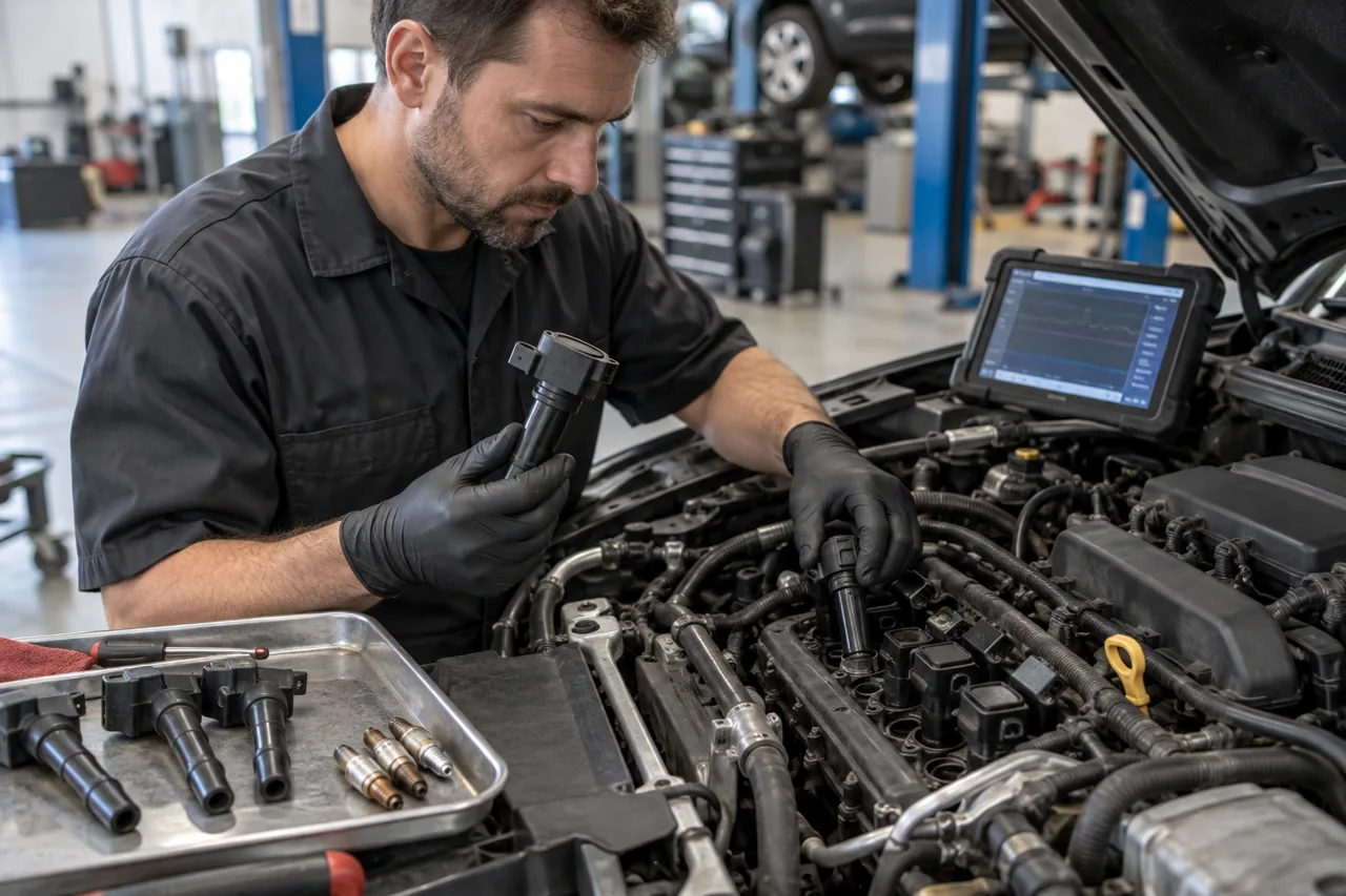
Compare cylinders under the same engine condition and with known system architecture. A tall firing-voltage pattern can reflect excessive plug gap, lean mixture, high cylinder pressure, poor connection or insulation; a low requirement can reflect fouling, low compression or rich mixture. Oscilloscope patterns require correct attenuation, probe orientation, time base and reference data. Do not interpret one screenshot or generic waveform as a universal pass/fail specification.
A controlled swap can help—but must preserve evidence and risk
Moving a coil to another cylinder may be useful when the components are identical, accessible, safe to exchange, and the misfire can be reproduced consistently. Mark original positions, inspect boots and wells, avoid spreading oil, coolant or moisture, clear nothing until baseline evidence is saved, and repeat the same operating condition. A code that follows the coil strengthens the case but still warrants inspection of its boot, terminal and plug load.
Do not swap a visibly damaged, overheated or contaminated component into a healthy location, force mismatched connectors, or use swapping when removal risks seized plugs or fragile wiring. An intermittent fault may appear to move by chance, and changing parts can improve a poor connection temporarily. If the code stays, continue with connector, command, plug, injector, compression and intake checks rather than concluding that every coil should be replaced.
Removed spark plugs preserve cylinder-specific evidence
Keep plugs in exact cylinder order and inspect the terminal, ceramic, shell, seat, threads, gasket where used, ground and center electrodes, gap, deposits, cracks, flashover marks, heat damage and signs of fuel, oil, coolant or foreign material. Bosch links carbon, oil and ash fouling, severe wear, melting and cracked insulators with different mixture, maintenance, oil-control, thermal, detonation or handling conditions.
Appearance is evidence, not a complete diagnosis. Recent idling, a cylinder that did not fire, fuel and oil additives, plug design, engine temperature and cleaning can change deposits. A fuel-wet plug may be the result of missing ignition rather than a leaking injector. Oil or coolant can foul a healthy new plug and overload a coil. Measure and photograph useful findings, then correct the air, fuel, thermal or mechanical cause before installing replacements.
Gap and wear change the voltage demanded from the coil
Electrode erosion increases gap over time and generally increases the voltage required to initiate the spark. NGK notes that a worn wider gap can strain the ignition system. But automatically regapping every modern fine-wire plug is not safe: some manufacturers supply a fixed gap, prohibit adjustment, or require a specific method that protects the center and ground electrodes. A dropped or mishandled plug may hide an insulator crack.
Measure only with an appropriate tool and compare with exact specifications. Do not pry against a fine center electrode, apply abrasive blasting that leaves media or damages coatings, or use a hotter or colder plug as a shortcut for oil, mixture, timing or cooling faults. Plug heat range manages firing-end temperature; it does not increase spark energy. Modified engines need calibration-specific expertise rather than extrapolation from stock specifications.
Fuel, air, compression, and timing can defeat healthy ignition parts
An injector that is restricted, leaking or not commanded; low or unstable fuel pressure; contaminated fuel; intake leakage; uneven air distribution; exhaust restriction; EGR flow; valve deposits; low compression; leakage past a valve, ring or head gasket; incorrect valve timing; oil or coolant entry; or control strategy can create identical cylinder symptoms. Compare injector command or contribution, fuel correction, pressure, compression or leak-down and timing evidence as the pattern supports.
A spark tester showing a spark in open air does not prove adequate energy in a pressurized cylinder. Conversely, a cylinder contribution test or disabled injector identifies effect without naming cause. If a new plug temporarily improves operation, the initiating deposit or gap problem may remain. The final recommendation should say whether the work is scheduled maintenance, a confirmed ignition repair, a correction of contamination, or one step in a documented diagnostic path.
Replacement scope follows evidence—not an automatic all-coil rule
Scheduled plug replacement often applies to the full engine using an exact matched set. Coil replacement can be one supported unit, a multi-coil assembly, or a broader age and risk decision explained separately. Proximity and equal mileage do not prove that every individual coil failed. Compare the cost and access of replacing one versus a documented set, but do not represent preventive choice as diagnostic necessity.
Define plugs, coils, boots, leads, springs, seals, connector or terminal repair, valve-cover or well leak correction, intake components removed for access, gaskets, one-time fasteners and any adaptations. If one bank requires major duplicated access, state it. Preserve reusable component locations where design or learned data matters, and avoid low-quality mismatched ignition parts that change fit, resistance, electromagnetic compatibility or thermal behavior.
Installation protects threads, ceramics, boots, and electrical connections
Work on an engine at the specified temperature, remove debris before extracting plugs, and use controlled access so dirt cannot enter the cylinder. Start plugs by hand or with a method that confirms thread engagement; inspect suspicious resistance rather than forcing it. Use the specified dry or prepared-thread condition and torque or angle procedure. Unapproved anti-seize can change clamp load, heat transfer and removal behavior.
Seat boots and electrical connectors fully, apply only specified dielectric material in the specified location, route wires and harnesses away from heat and abrasion, and torque coil and intake hardware appropriately. Excess grease can insulate contacts or create hydraulic effects, while grease on plug electrodes is contamination. Reconnect grounds, hoses and seals disturbed for access and visually account for tools before the first start.
Verification must recreate the original load and protect the catalyst
On initial start, monitor oil pressure and abnormal noise, then confirm smooth operation, stable voltage, plausible fuel correction and falling or absent cylinder misfire counts. Inspect for intake leakage, oil or coolant in wells, arcing, loose connectors and new codes. A smooth warm idle does not verify a fault that originally occurred only during cold start, rain, hot soak, boost or highway load.
Repeat the original condition safely while graphing relevant data, and verify no flashing warning, power loss, catalyst-overtemperature evidence or recurring cylinder fault. Evaluate permanent codes and readiness rather than promising immediate monitor completion. Document plug part number and gap policy, torque method, coil or wiring findings, contamination corrections, pre/post data and remaining follow-up. If a misfire returns, preserve the new evidence instead of repeating the same replacement.