
Fuel and evaporative-emissions technical guide
Fuel delivery and fuel-vapor control share a tank—but require different diagnosis
A hard start, stall, loss of power, pump noise, low-pressure code, check-fuel-cap message, fuel odor, or EVAP leak code can involve separate liquid-fuel, electrical, engine-control, or vapor-management faults. Replacing the pump, filter, or cap from a symptom or code skips the evidence needed to distinguish supply voltage, pressure and volume, contamination, injectors, tank venting, seals, valves, lines, and the conditions under which the monitor runs.
Treat liquid fuel, strong vapor, heat, and electrical sparks as hazards
Stop safely and shut the vehicle down for visible fuel leakage, a strong persistent fuel odor, smoke, fire, a damaged tank or line, or fuel contacting hot exhaust or electrical components. Do not start the engine, operate switches, create sparks, smoke, or use an unsuitable light near a suspected leak. Move people away and use emergency or recovery assistance appropriate to the condition rather than driving to “see if it clears.”
Fuel systems can retain pressure after shutdown, tanks contain flammable vapor, and pump circuits carry meaningful current. High-pressure gasoline direct injection and common-rail diesel systems can cause injection injury and require specified depressurization, protective equipment, cleanliness and testing tools. Hybrids may start the engine automatically, and alternative-fuel or high-voltage vehicles add separate hazards. Exact service information must control access and isolation.
Define the complaint before choosing a component test
Record whether the engine cranks, starts and stalls, needs extended cranking, loses power only under load, fails hot or cold, hesitates after refueling, produces unusual pump noise, shows a fuel-cap message, or sets a warning after a particular drive or soak. Note fuel level, recent refueling, wrong-fuel possibility, weather, collision or underbody impact, battery work, prior pump or filter work, and whether a different key, jump-start or added fuel changed the result.
A no-crank is not a fuel-pump symptom. A crank-no-start can involve authorization, ignition, injector command, compression, timing, airflow, contaminated fuel, supply pressure, rail pressure, or control. An EVAP code usually describes vapor-system integrity or flow and need not affect liquid delivery. Preserve confirmed, pending and permanent codes, freeze frame, readiness, pressure commands and relevant data before clearing or opening the system.
Identify the exact fuel architecture and serviceable parts
Determine gasoline, diesel, flex-fuel or another approved fuel; port or direct injection; low-pressure transfer and high-pressure stages; return or returnless control; mechanical or electrical high-pressure pump; external or in-tank filtration; replaceable module, controller and pressure sensor; saddle tank or multiple pumps; and cap, capless or remote-filler EVAP design. The same symptom can require very different pressure, flow, cleanliness and safety procedures.
A “fuel filter” may be a scheduled external part, an in-tank strainer, part of a pump module, a diesel water separator, a high-pressure protection stage, or not separately serviced. A “fuel pump” may describe the tank pump, transfer pump, high-pressure pump, jet pump or complete module. A “fuel cap” may not exist on a capless design. The estimate and test plan must name the actual component and function.
Verify supply, ground, command, and current before condemning an electric pump
Listen for pump operation only as an initial observation. A quiet pump may lack command, power or ground, while a noisy pump can still produce pressure. Check battery condition, fuses, relays or solid-state control, inertia or crash strategy where equipped, immobilizer authorization, module communication, pump command, connector heat or corrosion, and voltage drop on both sides of the circuit under load. A meter showing battery voltage on an unloaded wire does not prove current can flow.
Measure current and, when useful, inspect the current waveform under a defined operating condition. Delphi notes that pressure and volume alone may not reveal every pump condition; waveform consistency can provide mechanical and electrical evidence. High or low current is not self-explanatory: restriction, low voltage, poor ground, worn commutation, fuel level, temperature, controller duty cycle and pump design affect it. Compare with application information and other measurements.
Pressure, flow, residual pressure, and rail command answer different questions
Use the specified connection, equipment, units, pressure range and safety method. Observe prime, cranking, idle and load as relevant; compare desired and actual pressure where the system reports them. Adequate static pressure does not prove adequate flow under demand, and a momentary key-on reading does not establish performance during acceleration. A restricted filter, weak pump, blocked line, failed regulator, controller limit, tank pickup or venting issue can produce overlapping results.
Residual pressure loss after shutdown can involve a pump check valve, regulator, injector leakage, line leak or measurement setup. Direct-injection high pressure depends on sufficient low-side supply, pump actuation, control valves, sensors, rail integrity and engine mechanical drive. Do not loosen a line to “see whether fuel comes out,” bypass safety controls, or command maximum pressure without the manufacturer procedure. Record conditions and compare multiple stages before replacing one.
A filter restriction must be measured or supported by maintenance evidence
For a scheduled serviceable filter, verify the exact interval, time, mileage, fuel and severe-use assumptions from current vehicle information. For a suspected restriction, compare pressure or vacuum before and after the filter, volume under relevant load, pump current and known contamination as the system allows. A restricted strainer or collapsing line can resemble an external filter, while low supply voltage can make an unrestricted system appear weak.
Inspect removed fuel safely for water, rust, dirt, biological material in diesel, metal, wrong fuel or tank deterioration when symptoms justify it. Preserve the orientation and contents as evidence. Installing a filter without finding the contamination source can provide only temporary relief. Use the specified flow direction, seals, connector locks, mounting, priming and bleeding method; uncontrolled pre-filling can introduce unfiltered material on some designs.
Contamination changes the scope beyond one pump or filter
Wrong fuel, water, rust, tank coating, dirt, microbial growth, metal from a failing high-pressure pump, or debris from a damaged module can circulate into lines, rails, injectors, regulators and return paths. Delphi documents cases in which replacing only an in-tank module leaves debris that causes repeat failure. Diagnose where contamination began, how far it travelled, which components can be cleaned or tested, and which must be replaced under the exact procedure.
The estimate should state tank access and condition, draining and lawful disposal, cleaning criteria, pump or module, strainer and filter, seals and locking ring, damaged connector or controller, lines, high-pressure components, injectors, fuel quantity and quality, programming or adaptation, and follow-up sampling. Do not promise that a generic additive or one filter will repair abrasive metal damage, phase-separated fuel, corrosion or a contaminated high-pressure system.
Fuel-cap and EVAP diagnosis begins with the entire vapor boundary
EPA describes a loose or missing cap as one possible OBD trigger, not the only cause of an EVAP warning. Inspect the correct cap or capless seal, filler neck, hinge and closure, tank and pump-module seals, vapor lines, canister, purge and vent valves, leak-detection pump or natural-vacuum hardware, pressure sensor, wiring and damage from overfilling or impact. Confirm that an aftermarket cap has the correct sealing, pressure and vacuum behavior for the application.
A cap that was left loose may be secured and monitored through subsequent trips according to the owner information, but replacing a cap without testing is not a complete response to every small- or large-leak code. EPA distinguishes a cap test, system pressure test and OBD EVAP check because they answer different questions. A cap can pass while another leak exists, and an EVAP code can involve flow or electrical performance rather than an opening to atmosphere.
Smoke, pressure, vacuum, purge, and vent tests require controlled limits
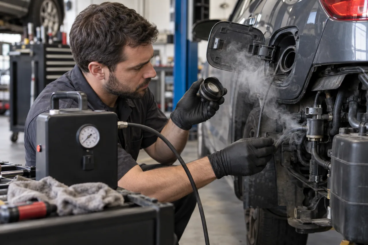
Review code criteria and freeze frame because EVAP monitors run only under defined fuel level, temperature, soak and drive conditions. Inspect first, then use an approved low-pressure smoke or inert-gas method, pressure or vacuum decay, component actuation, pressure-sensor data, flow checks or isolated testing as appropriate. Never use shop air or excessive pressure on a fuel tank, and keep ignition sources away.
Temperature and fuel vapor change tank pressure, so an apparent decay is not automatically a leak. A closed vent can falsely hold pressure; an open purge path can move vapor into the engine; a saturated canister, liquid fuel from repeated topping off, restricted filter, cracked hose or faulty sensor can distort results. Seal tools and adapters are part of the test boundary and must be checked before condemning the vehicle.
Replacement scope must prevent leaks, electrical heating, and repeat failure
For tank access, control fuel quantity, support the tank correctly, protect lines and wiring, ventilate the area, and inspect the access cover or tank straps, filler and vent connections. Replace specified seals, locking devices, one-time hardware and damaged connectors; clean the sealing surface without introducing debris. A discolored terminal, melted flange or overheated ground requires circuit and connector correction, not only a new pump.
Confirm module orientation, float movement, hose and harness routing, line connector engagement, tank seal seating, filler integrity and cap or capless closure. Program or calibrate a controller, fuel-level sender, composition sensor or pressure system only when specified. Use approved fuel and priming steps; repeated dry cycling can damage some pumps. On high-pressure systems, observe cleanliness, line reuse restrictions, torque and leak-test procedures exactly.
Verification covers delivery, sealing, drivability, and monitor completion
After repair, check for liquid and vapor leaks before and during controlled operation, verify supply voltage and current where relevant, and compare pressure, volume or desired-versus-actual response under the original cranking, idle and load conditions. Confirm start time, idle, acceleration, hot restart, fuel level indication, pump noise and warning status without creating an unsafe high-load test. Reinspect all disturbed connectors, lines and tank or access areas.
For EVAP work, verify cap or closure sealing, purge and vent command and response, pressure-sensor plausibility and system integrity using the applicable test. Clearing a code does not prove the readiness monitor will pass; explain the drive and soak conditions, permanent-code behavior and follow-up. A complete record identifies the failed relationship, test evidence, contamination findings, parts and seals installed, fuel handled, safety limitations, and how both the original symptom and connected system were verified.