
Exhaust and emissions technical guide
Exhaust, oxygen-sensor, and catalyst faults must be tested as one system
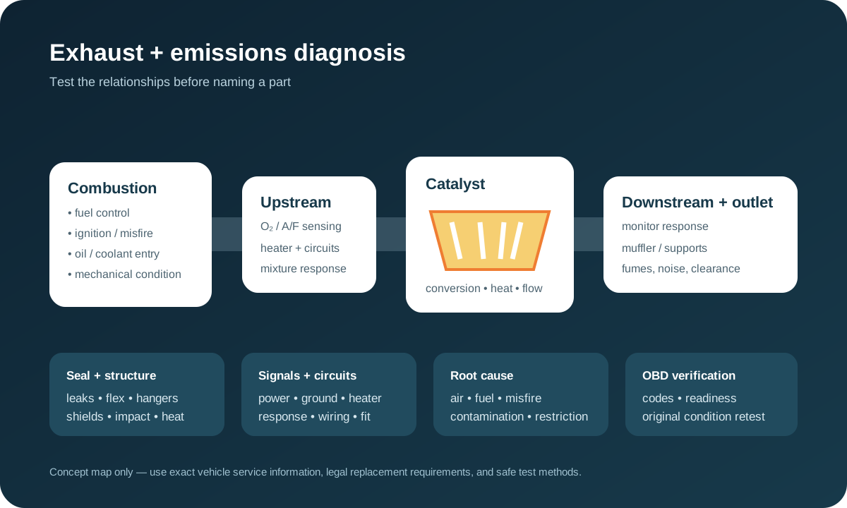
An exhaust noise, odor, oxygen-sensor code, loss of power, or catalyst-efficiency code does not identify a single failed part. Exhaust sealing and flow, combustion, fuel control, sensor circuits, catalyst chemistry, temperature, software, and OBD monitor conditions affect one another. A defensible repair preserves the evidence, protects people from fumes and heat, tests upstream causes, and verifies the complete system instead of replacing the component named in a code.
Treat fumes, fire risk, loose parts, and severe restriction as urgent
Move to fresh air and stop safely if exhaust fumes enter the cabin, anyone develops headache or dizziness, a hot component contacts fuel, oil, wiring or trim, a pipe drags, a shield or converter glows, or the vehicle loses power severely. Carbon monoxide cannot be judged by smell. Do not idle in a garage or enclosed area to reproduce an odor, and do not crawl under a vehicle supported only by a jack.
A flashing engine warning with severe shaking can indicate a catalyst-damaging misfire. Continued driving can overheat the converter or surrounding structure. A blocked exhaust can also produce extreme heat and poor power. Shut the engine down when safe, keep combustible material away, and arrange recovery when the exhaust is insecure, fumes persist, temperature rises abnormally, or the vehicle cannot maintain safe speed.
Record the exact symptom and operating condition before clearing evidence
Document whether the concern is a tick, hiss, rasp, boom, rattle, whistle, odor, warning lamp, failed monitor, reduced power, poor economy, or visible damage. Note cold start versus hot operation, idle versus load, acceleration, deceleration, road speed, engine speed, ambient temperature, recent impact or repair, and whether the sound changes with steering, body movement, or gear selection.
Record confirmed, pending, and permanent diagnostic codes, freeze-frame data, readiness status, fuel corrections, oxygen or air-fuel sensor data, misfire information, and relevant temperature or pressure data before disconnecting power or clearing codes. A fault may occur only during cold-start catalyst heating, closed-loop operation, a high-load event, or the enable conditions for a non-continuous monitor. Immediate silence or an extinguished lamp after clearing does not prove a repair.
Inspect the exhaust as a supported, sealed, heat-managed structure
Trace the system from the cylinder head or turbo outlet through manifolds, flex sections, flanges, gaskets, pipes, catalysts, resonators, mufflers, joints, clamps, hangers, shields, sensor bungs, and tailpipe. Look for soot trails, cracks, impact damage, corrosion, melted or missing material, distorted flanges, failed welds, broken studs, stretched hangers, contact marks, water entry, and heat damage to nearby hoses, wiring, floor, fuel or brake components.
Exhaust moves as the powertrain rocks and the body flexes. A leak or rattle may open only cold, hot, under torque, or over bumps. Condensation dripping from a drain or tailpipe can be normal, while black soot at a joint supports leakage. Locate noise with safe equipment and controlled operating conditions; blocking the tailpipe, using open flame, or applying uncontrolled pressure can create injury, damage, or misleading results.
Leak position matters because outside air can distort sensor evidence
A leak upstream of an oxygen or air-fuel sensor can draw oxygen into exhaust pulses and bias the reported mixture even when combustion is not lean. A leak between sensors can alter the pattern used for catalyst monitoring. A downstream leak may have less effect on fuel control but can still create fumes, noise, water intrusion, or structural failure. Identify the leak relative to every sensor and converter instead of treating all holes alike.
Smoke, low-pressure testing, visual evidence, sound tools, gas analysis, or sensor behavior may help, but each method must suit the vehicle and remain within safe limits. Heat can close a crack, pressure can move a flex joint, and fan airflow can carry fumes away from the source. Repair sealing and support faults, then repeat the relevant data capture before deciding that the sensor or converter is defective.
Upstream and downstream sensors have different monitoring jobs
An upstream oxygen or wide-range air-fuel sensor primarily helps the controller evaluate mixture and fuel correction. A downstream sensor commonly contributes to catalyst monitoring and may also support control strategies defined by the manufacturer. Some engines have several banks, converters, and sensors. Bank and sensor numbering, connector location, and appearance must be confirmed from exact application information—not guessed from left, right, front, or rear.
A conventional narrow-band oxygen signal, a wide-range current-based sensor, and a downstream monitor are not interpreted with the same expected values. Switching activity alone is not a universal pass/fail test. Compare the correct parameter identifiers with commanded mixture changes, fuel trims, load, temperature, and known-good or service limits. A sensor reporting a real lean, rich, misfire, or exhaust-leak condition is doing its job even when its value looks abnormal.
An oxygen-sensor code is a circuit or performance direction—not a parts order
Sensor-related codes can describe heater current, response time, range, bias, correlation, activity, or circuit integrity. Possible causes include power supply, fuse, relay, ground, high resistance, shorting, connector contamination, heat-damaged harness, incorrect routing, exhaust leakage, mixture faults, sensor contamination, the wrong part, or control-module strategy. Test the code definition and circuit for the exact vehicle before removing a sensor.
Verify supply and ground under load, heater resistance or current only by the specified method, signal integrity, reference or pump-cell circuits where applicable, connector terminal fit, harness movement, and response under controlled operating conditions. Avoid piercing weatherproof insulation unnecessarily. Anti-seize, sealant, silicone, coolant, oil, fuel additives, and impact can affect some sensors; a contaminated sensor may be consequence rather than root cause.
Fuel control and engine condition must be judged before the catalyst
Rich or lean operation, ignition misfire, injector leakage or imbalance, incorrect fuel pressure, unmetered air, purge flow, airflow or pressure measurement, valve timing, compression, oil consumption, coolant entry, and exhaust leakage can change both sensor traces and catalyst temperature. Review short- and long-term correction by bank under relevant speed and load, but do not interpret one trim value without knowing operating mode and manufacturer strategy.
A catalyst can be damaged by unburned fuel, oil, coolant, impact, overheating, or prolonged mixture error. Correct the supported upstream fault before installing a converter or the replacement may fail again. If deposits, a melted substrate, or contamination are present, document the likely initiating condition and determine whether engine repair, extended verification, or further testing is necessary before the emissions repair can be considered durable.
A catalyst-efficiency code reports monitor performance, not automatic replacement
OBD catalyst monitoring compares system behavior during defined enable conditions. A code such as an efficiency-below-threshold result means the monitor did not observe the expected oxygen-storage or conversion behavior; it does not by itself prove the converter is the only cause. Exhaust leaks, biased or slow sensors, heater faults, fuel control, misfire, contamination, incorrect software or parts, and incomplete prior repairs can influence the result.
A useful diagnosis checks for related faults and service information, verifies exhaust sealing, evaluates upstream and downstream sensor response, confirms engine and fuel control, and assesses temperature, emissions, or oxygen-storage behavior with application-appropriate methods. An inlet-to-outlet temperature difference alone is not a universal converter verdict because load, mixture, airflow, catalyst design, and measurement position affect temperature. The conclusion should explain what was tested and what alternatives were excluded.
Restriction, broken substrate, and external rattles need separate proof
Loss of power at higher load, abnormal manifold pressure, excessive heat, a whistle, or a vacuum pattern can support exhaust restriction, but similar symptoms occur with air, fuel, ignition, boost, transmission, and mechanical faults. Backpressure, pressure-drop, temperature, scan-data, or controlled comparison tests can help when interpreted against the correct specification. Do not drill components or create a leak merely as an uncontrolled shortcut.
A rattle can come from loose shields, hangers, double-wall pipe, baffles, mounts, brackets, or broken catalyst material. Confirm its source cold and hot and under safe movement conditions. A broken substrate may shift and restrict intermittently even if the shell looks intact. External impact can damage the converter without creating an efficiency code immediately, while an efficiency code can occur without any audible rattle.
Repair scope includes fit, fasteners, wiring, shields, and legal configuration
Define the exact replacement by vehicle identification, engine, emissions label, converter location, sensor type, certification and application catalog. The U.S. EPA prohibits removing or defeating required emissions controls and identifies straight-pipe replacement and OBD defeat as tampering examples. Restoring the certified configuration is different from hiding a fault with spacers, simulators, software, hollow components, or monitor suppression.
Inspect studs, threads, flanges, gaskets, flex joints, hangers, heat shields, sensor bungs, connectors, harness clips, and nearby heat protection. Corroded fasteners can expand labor and may require controlled extraction or thread repair. Route sensor wiring away from the pipe and movement, use specified compounds and torque, preserve required shields, and verify clearance through powertrain movement. The estimate should state whether adjacent damage, seized hardware, or upstream repair changes the scope.
Verification includes sealing, operation, readiness, and the original complaint
After repair, inspect every disturbed joint and support cold and hot, confirm no cabin fumes or unsafe heat exposure, and reproduce the original noise, load, power, or warning condition safely. Review fuel correction, sensor response, heater operation, misfire data, temperatures, and codes relevant to the diagnosed fault. A new component and cleared memory are not outcomes until the system behaves correctly.
Readiness monitors may require specific soak, temperature, fuel-level, speed, load, and deceleration conditions; the applicable service information governs the drive pattern. Do not promise that one generic drive cycle will complete every monitor, and do not clear memory repeatedly to chase readiness. Report which monitors completed, which remain not ready, whether permanent codes changed according to OBD logic, and what follow-up is needed. Final documentation should connect the initial evidence, root cause, authorized work, and measured verification.