Emissions diagnosis
Repair the condition that caused the emissions monitor to fail—not just the code
An emissions warning can involve air and fuel measurement, combustion, exhaust sensing, catalyst performance, evaporative containment, exhaust-gas recirculation, secondary air, diesel aftertreatment, wiring, software, or mechanical engine condition. The diagnostic path must show which monitored relationship failed and why.
Washington ended periodic testing, not the need for correct operation
Washington’s Department of Ecology states that the vehicle emissions-check program ended January 1, 2020, so testing is no longer required before renewing registration. The same agency also states that modified emissions equipment or a smoking vehicle remains unlawful. A local repair discussion should therefore not pretend that a former state inspection is still required, yet it should not present disabled controls as an acceptable shortcut.
The U.S. EPA explains that federal law prohibits tampering with emission-control devices and the manufacture, sale, or installation of defeat devices. This page does not advise deleting hardware, suppressing codes, altering readiness, or calibrating around a fault. The goal is to restore the certified system’s function using the correct parts, software, procedures, and evidence for the vehicle.
Preserve codes, freeze frame, and readiness before clearing
Record the exact warning, confirmed, pending, and permanent codes, freeze-frame conditions, readiness status, and relevant live data before clearing anything or disconnecting power. Note whether the light is steady or flashing, how the engine runs, fuel level, outside temperature, recent refueling or battery work, repairs, modifications, and the condition in which the warning appeared.
Clearing codes removes useful evidence and resets readiness monitors. A lamp that stays off immediately after clearing is not proof of repair because many non-continuous monitors require specific temperature, speed, load, fuel-level, soak, and driving conditions before evaluating the system again. Permanent-code behavior and readiness completion also follow defined logic; they should not be treated as switches a scan tool can simply erase.
Fuel-control faults begin with measured relationships
Rich or lean codes describe fuel correction or mixture behavior beyond the control system’s expected range. Possible causes include unmetered air, intake or exhaust leaks, incorrect air measurement, biased pressure or temperature data, fuel-pressure or injector faults, purge flow, ignition misfire, oil or coolant contamination, mechanical sealing, and wiring. An oxygen-sensor response may accurately report a problem created elsewhere.
Compare short- and long-term correction, oxygen or air-fuel sensor behavior, airflow, manifold pressure, load, temperature, commanded purge, fuel pressure where appropriate, and cylinder contribution under the condition in the freeze frame. Inspect the complete air and exhaust path. Replacing the component named in a code without testing can leave the real leak, fuel, electrical, or mechanical cause unchanged.
Misfire can damage the catalyst and needs a safe priority
A flashing engine warning with severe shaking can indicate a catalyst-damaging misfire. Reduce risk by stopping safely rather than driving until the light becomes steady. Misfire diagnosis can involve ignition, injection, fuel quality or pressure, air distribution, compression, valve timing, deposits, cooling intrusion, wiring, module command, or a combination. Cylinder counts identify where combustion was detected as irregular, not automatically which part failed.
Preserve the conditions, then compare ignition and injector control, plug condition, fuel delivery, compression or leak-down where supported, mechanical timing, and relevant sensor data. If raw fuel or oil reached the catalyst, correct the upstream cause before judging the converter and include contamination consequences in the repair plan. A new catalyst installed ahead of an active misfire may be damaged again.
Catalyst efficiency codes require upstream and downstream evidence
A catalyst monitor compares system behavior under enabling conditions; its code does not prove that every converter with that code must be replaced immediately. Exhaust leakage, sensor performance, fuel control, misfire, oil or coolant consumption, temperature, incorrect parts, wiring, and software can influence the result. Inspect and correct supported upstream faults before reaching a final catalyst conclusion.
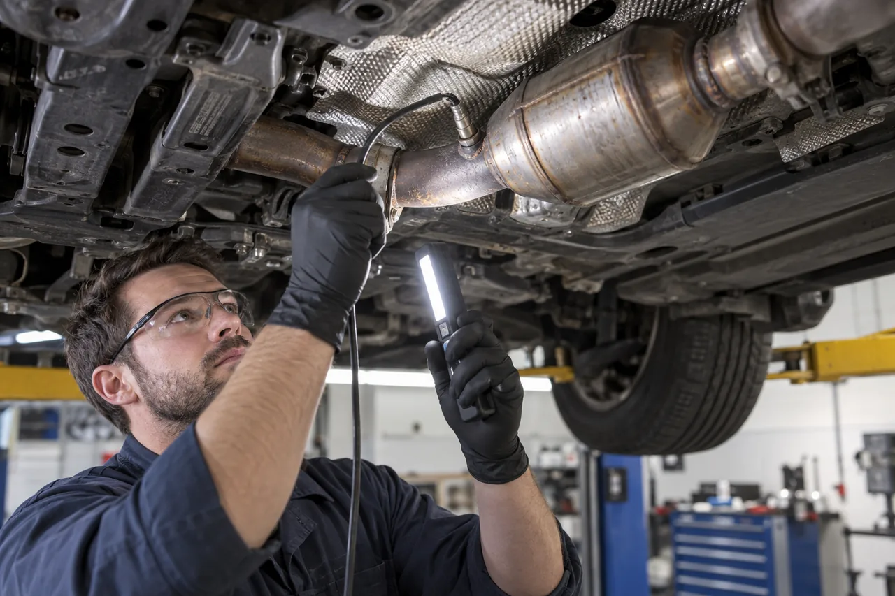
Testing may include leak inspection, sensor response and heater circuits, fuel-control review, temperature or gas analysis where appropriate, monitor history, and confirmation that the correct converter and calibration are present. If replacement is supported, verify exact application, emissions certification, installation hardware, surrounding exhaust condition, and why the original unit failed. The final verification must allow the relevant monitor to run.
EVAP diagnosis must control fuel level, sealing, and test conditions
The evaporative system contains fuel vapor rather than releasing it freely. A loose or damaged cap can cause some faults, but valves, pumps, pressure sensors, lines, canister, tank seals, filler components, wiring, and incorrect purge flow can produce overlapping codes. Gasoline vapor is flammable; improvised pressure, smoke, bypass, or open-flame methods are unsafe.
Use the vehicle procedure and approved test equipment, observe fuel-level and temperature limits, command components when supported, evaluate pressure change, and isolate the leak or flow fault without exceeding system pressure. A smoke source can reveal a path but does not prove every valve’s dynamic operation. After repair, confirm sealing and operation while recognizing that the monitor may require a soak and defined drive conditions.
EGR, secondary air, and diesel aftertreatment need system-specific tests
EGR faults may involve flow restriction, valves, coolers, pressure or temperature sensing, vacuum or electrical control, intake deposits, exhaust restriction, or software. Secondary-air faults can involve pumps, valves, passages, relays, power, grounds, and oxygen-sensor response during a cold-start test. Parts should be tested in the phase when the controller actually uses them.
Diesel systems can add particulate filters, oxidation or SCR catalysts, reductant quality and delivery, differential-pressure and temperature sensing, EGR, turbo and air handling, and regeneration requirements. A soot or ash estimate, derate, or reductant warning is not resolved safely by deleting a monitor. Identify the initiating engine, sensor, dosing, temperature, duty-cycle, or hardware fault and follow the application-specific service and safety procedure.
Leaks, sensors, wiring, and software can imitate failed hardware
Small intake or exhaust leaks can change sensor readings without being obvious at idle. Heater, power, ground, reference, signal, connector, and harness faults can make a healthy sensor appear implausible. Low vehicle voltage or network problems can create multiple secondary emissions codes. Verify circuits under relevant load and compare signals to operating conditions before condemning modules or aftertreatment.
Manufacturer updates, adaptations, learned values, and parts calibration may matter, but software should not be used to mask a physical fault. Confirm whether a published procedure or update applies to the exact VIN and configuration. After battery or module work, distinguish an incomplete monitor from a failed monitor, and document any reset or relearn performed.
A complete estimate names cause, legal configuration, and verification
The recommendation should identify the failed monitored relationship, supporting tests, root cause, parts and labor, damaged wiring or plumbing, gaskets and fasteners, software or adaptation, and whether upstream contamination or engine work is required. It should also state uncertainties and which findings could change the scope. Compare estimates only when they restore the same legal configuration and include equivalent verification.
After repair, repeat the relevant cold start, idle, cruise, load, refueling, or soak condition safely; review fuel control and sensor behavior; check leaks; confirm warning status; and complete the necessary monitor or drive cycle without promising an instant readiness result. Retain pre- and post-repair codes, data, parts information, and verification. A cleared lamp is a step; a monitor that evaluates the repaired system successfully is stronger evidence.