
Fuel delivery diagnosis
Prove the fuel-delivery fault before replacing a pump
A crank-no-start, stall, hesitation, low power, noise, pressure code, or lean condition can involve fuel quantity or quality, electrical supply, an in-tank pump, controller, filter, regulator, pressure sensor, high-pressure pump, injector, air metering, ignition, compression, or engine control. The word “fuel” in a symptom or code does not identify the failed part.
Treat fuel odor, visible leakage, or smoke as an immediate safety concern
Stop safely, shut the engine off, keep ignition sources away, and leave the area when fuel is spraying, dripping rapidly, pooling, producing strong vapor, or reaching hot exhaust or electrical components. Do not cycle the key repeatedly to “see where it leaks,” use an incandescent work light, smoke nearby, or continue driving because the engine still runs. Arrange suitable recovery when the system cannot be made safe.
Fuel systems can retain pressure after shutdown, and gasoline vapor can ignite far from the visible liquid. Exact depressurization, battery isolation, ventilation, lifting, tank support, approved containers, personal protection, and fire-control procedures depend on the vehicle and workplace. Diesel fuel presents different ignition and injection hazards; common-rail pressure can cause serious injection injury. Follow model-specific service information rather than a generic shortcut.
Define whether the engine does not crank, cranks without starting, stalls, or loses power
A no-crank condition begins with battery, starting, security, range or clutch input, and control diagnosis—not a fuel pump. For a crank-no-start, record cranking speed, immobilizer status, engine-speed signal, compression or timing clues, ignition or diesel enable, injector command, fuel pressure, and whether the fault is cold, hot, intermittent, or related to fuel level. Starting-fluid experiments can be hazardous and misleading.
For a stall, hesitation, extended crank, surge, or low-power complaint, note load, speed, temperature, incline, cornering, fuel level, recent refueling, weather, and how long the vehicle sits. A restricted exhaust, ignition breakdown, airflow error, vacuum leak, weak battery, charging fault, injector problem, mechanical timing, or module strategy can resemble inadequate fuel. Reproduce the original event safely before selecting a component.
Identify low-pressure, high-pressure, gasoline, and diesel stages
Port-injected gasoline systems commonly use an electric tank module to supply the rail at a controlled pressure. Gasoline direct injection adds an engine-driven high-pressure pump and much higher rail pressure. Diesel systems may use a lift stage, filter and water management, high-pressure pump, rail, control valves, and injectors with strict cleanliness requirements. Some vehicles use multiple tanks, transfer pumps, saddle-tank jet pumps, variable-speed modules, or returnless control.
The tank module may combine the pump, reservoir, strainer, level sender, pressure regulation, jet pump, filter provisions, flange, seals, and electrical pass-throughs. Bosch describes these as a connected supply system rather than a motor alone. Confirm VIN, engine, fuel type, system layout, specified test points, pressure units, and serviceable assemblies before ordering parts or connecting equipment.
Preserve scan data and prove electrical command under load
Read all relevant powertrain, body, fuel-pump-control, security, and network modules before clearing anything. Record confirmed, pending, and permanent codes; freeze frame; commanded and actual low- and high-side pressure; pump duty or speed; rail-pressure control; voltage; engine speed; mixture correction; and related air, timing, or misfire data available on that vehicle. A pressure-sensor or pump-control code defines a monitored condition, not automatically a failed sensor or pump.
Use the correct diagram to test fuses, relay or solid-state controller, power, ground, command, feedback, connectors, splices, and harness routing. Measure voltage drop with the circuit carrying its relevant load; an unloaded voltage reading can hide resistance. Delphi failure analysis links overheated module terminals and poor body-harness connections with reduced pump performance and repeat failure. Current or scope analysis can reveal motor irregularities, but specifications and access method remain application-specific.
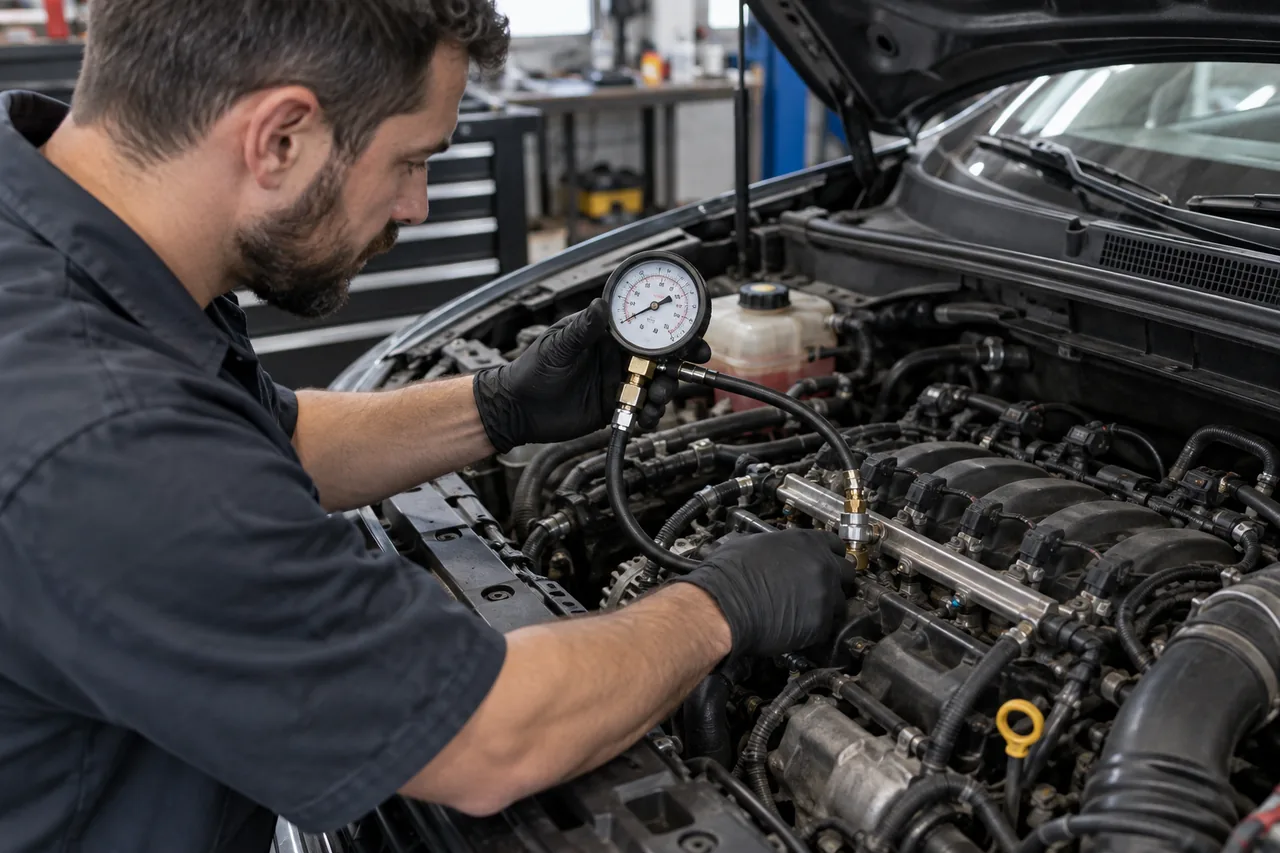
Measure pressure, volume, residual pressure, and response in the failing condition
A single key-on pressure number is not a complete delivery test. Compare the proper low-side and, where applicable, high-side readings during prime, cranking, idle, snap throttle, sustained load, hot restart, and the operating condition that produced the complaint. Evaluate build time, regulated response, volume or flow, residual-pressure decay, and whether pressure follows command without unsafe connections or exceeding equipment ratings.
Low pressure may result from inadequate pump supply, restricted strainer or filter, a leaking line, incorrect regulation, weak electrical feed, tank venting, transfer failure, contamination, or excessive downstream leakage. Excessive pressure can also cause mixture and driveability faults. Rapid decay can involve a pump check valve, regulator, injector leakage, or an external leak. Isolate the sections with approved procedures instead of treating one gauge result as the identity of the failed part.
Inspect fuel quality, tank contamination, filters, and the failed part
Water, dirt, rust, microbial growth in some diesel applications, incorrect fuel, degraded fuel, metal, sealant, or other debris can restrict flow, damage pumps and injectors, and make a new component fail. Preserve a representative sample safely, inspect the tank and strainers, and document odor, separation, particles, corrosion, filter restriction, and where debris appears. Never use appearance alone to declare the entire system clean.
Delphi advises examining overheated terminals, the external strainer, module bucket, and internal strainer to understand why a pump failed; contamination can require tank cleaning or replacement and correction of the entry source. High-pressure pump damage can distribute metal through lines, rail, regulators, and injectors, making the repair scope vehicle- and failure-specific. Replacing only the in-tank pump cannot cure debris created elsewhere.
Define the replacement scope, seals, access, wiring, and fire-safe handling
State whether the estimate includes a pump motor, complete tank module, controller, relay, connector repair, filter, regulator, pressure sensor, high-pressure pump, follower, feed line, injectors, tank cleaning, contaminated fuel disposal, or tank replacement—and why each item is required. Access may be through a service opening or may require draining and supporting the tank, moving exhaust or driveline components, and replacing disturbed hardware.
Use the exact new seal or gasket, clean the flange area before opening it, protect the tank from falling debris, compare the replacement assembly and level arm, and follow specified retaining-ring or fastener procedures. Delphi cautions against sparks, recommends appropriate protection, and directs leak checking after installation. Some direct-injection lines, bolts, and seals are one-time-use; high-pressure work requires the published pressure-release and cleanliness method.
Verify pressure, leaks, fuel level, load response, and system readiness after repair
Before startup, confirm line locks, electrical connectors, tank straps or access cover, heat shields, exhaust clearance, harness routing, seals, fresh fuel, and that no tools or absorbent materials remain. Prime only as specified. Inspect for leakage during prime, cranking, running, and after shutdown without placing a hand near a suspected high-pressure leak. Confirm stable electrical supply, expected current or command, correct low- and high-side pressure response, and plausible level indication.
Repeat the original cold, hot, low-fuel, acceleration, restart, or road-load condition safely. Review codes, pressure tracking, mixture correction, misfire data, residual pressure, noise, odor, and readiness effects. Reinspect for leakage and disturbed components after a heat cycle. A successful repair documents both the corrected symptom and the evidence that the contamination, electrical, hydraulic, or mechanical cause will not immediately damage the replacement.