
Engine management service
Test airflow, fuel correction, and the intake before MAF service
Mass air flow service is not automatically sensor cleaning or replacement. Intake leaks, air-filter installation, wiring, contamination, fuel delivery, exhaust sampling, EGR operation, or mechanical faults can produce similar symptoms and data, so the repair must match more than one observation.
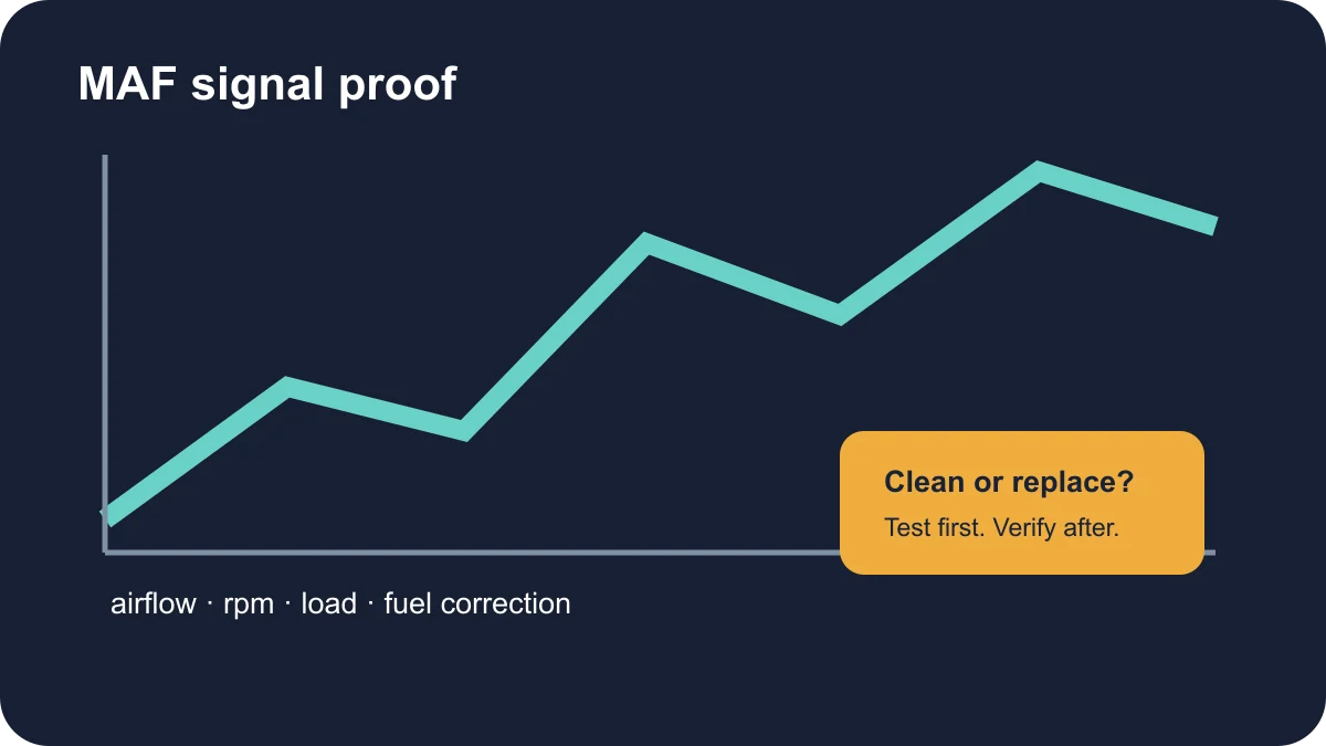
Quick decision: test before cleaning or replacement
Inspect the complete air path and connector, preserve codes and freeze-frame data, and compare airflow response with engine speed, load, fuel correction, pressure data where available, and the symptom. Cleaning is reasonable only when the sensor design and manufacturer procedure allow it and contamination—not circuit damage, element damage, an intake leak, or another engine fault—is supported by evidence.
Replacement is stronger when the circuit and air path pass, the signal remains implausible under a defined condition, and a suitable comparison or specified test confirms the sensor cannot report airflow correctly. An unplug test or temporary change in running does not prove that conclusion by itself because the control module may substitute a default strategy.
Begin with the symptom, not the component name
A driver may notice hesitation, unstable idle, stalling, reduced power, difficult starting, unusual fuel use, black exhaust smoke, or a check-engine warning. Those signs can fit an airflow-measurement problem, but none identifies the MAF sensor by itself. Record whether the concern occurs cold or warm, at idle or load, after rain or recent service, and whether the warning is steady or flashing.
Stop driving for severe shaking, a flashing engine warning, smoke, a strong fuel odor, or sudden loss of power that makes traffic operation unsafe. A vehicle that appears to run normally with a steady warning still deserves timely diagnosis because fuel-control errors can affect drivability and emissions-system components. Preserve the complete code and freeze-frame record before anything is cleared.
Understand what the airflow signal is used for
A common hot-wire MAF sensor sits in the intake path between the air filter and throttle body. It reports incoming airflow to the engine control unit, which evaluates that information with temperature, throttle, pressure, oxygen-sensor, speed, and other inputs when controlling fuel and engine operation. Some vehicles use different sensor arrangements, so the exact system must be identified before applying a generic test.
The displayed airflow value is evidence within a model, not a universal pass/fail number. Engine displacement, speed, load, altitude, temperature, valve timing, boost, and exhaust-gas recirculation can all change expected airflow. A plausible diagnosis compares the reading with vehicle-specific service information and with other data that should respond to the same operating change.
Inspect the air path before condemning the sensor
Check the air-filter installation, housing, ducting, clamps, seals, breather connections, and any point where unmeasured air can enter after the sensor. A torn boot, loose clamp, disconnected hose, damaged seal, or incorrect filter can distort the relationship between measured air and the air that reaches the engine. Restrictions and debris can also affect flow without creating an obvious electrical fault.
Inspect the sensing area only according to the applicable procedure. Touching a delicate element or applying an unsuitable cleaner can damage it. Contamination may be a result rather than the only cause, so look for a poorly fitted filter, oil or moisture source, intake damage, or previous service error before installing a replacement into the same conditions.
Use scan data and circuit tests together
The diagnostic plan can review confirmed, pending, and permanent codes; freeze-frame conditions; airflow response; short- and long-term fuel correction; oxygen or air-fuel sensor behavior; manifold pressure where equipped; throttle position; engine speed; temperature; and misfire information. A code for low, high, range, or performance behavior describes what the controller observed, not which part must be purchased.
Electrical checks may include connector condition, terminal fit, reference or supply voltage, ground under load, signal response, and wiring integrity. Bosch technical guidance notes that removing an air-mass unit during testing can change flow characteristics, which is one reason testing should preserve the intended installation. A substitution or unplug test can alter control strategy and should not be treated as proof by itself.
Worked scenario: high fuel correction at idle but less under load
Suppose fuel correction is strongly positive at idle, becomes smaller as airflow rises, and the MAF signal changes smoothly. That pattern can support looking for unmetered air that matters most at low flow, such as a split hose, crankcase-ventilation leak, or sealing fault, before condemning the sensor. A smoke test and physical inspection can then challenge that explanation.
If correction stays abnormal through load, the investigation can widen to measured airflow bias, fuel pressure or volume, exhaust sampling, injector behavior, and mechanical condition. The editorial judgment is to use the change across operating conditions to select the next test instead of treating one grams-per-second value as universal.
Separate airflow errors from fuel and mechanical faults
Fuel pressure, injector behavior, ignition misfire, exhaust leaks, oxygen-sensor feedback, compression, valve timing, crankcase ventilation, turbocharger plumbing, and EGR operation can shift the same data used to judge airflow. The strongest recommendation explains which competing causes were checked and why the remaining evidence supports the proposed repair.
A MAF reading that appears low may reflect genuinely reduced cylinder filling or an intake restriction; a reading that appears high may reflect the operating condition or a biased signal. Fuel corrections can point toward an air/fuel imbalance but do not identify whether the cause is air measurement, unmetered air, fuel supply, exhaust sampling, or combustion. Diagnosis should connect multiple observations rather than rely on a single graph.
Define and verify the repair scope
If replacement is supported, the estimate should identify the correct sensor or housing configuration, seals, clamps or damaged ducts, connector repair, air-filter correction, adaptation or reset procedure when specified, and any follow-up needed for related codes. Cleaning is not a guaranteed repair and may be inappropriate for a damaged or contaminated sensing element; the reason for choosing cleaning, repair, or replacement should be stated.
After work, check the complete intake for leaks, confirm the connector and duct are secure, repeat the original operating condition, and compare airflow and fuel response with the pre-repair evidence. Verify idle, acceleration, warning status, and any applicable readiness or drive-cycle requirement. For a deeper explanation of the data relationships and common diagnostic traps, continue to the mass-airflow guide.