
Engine-management guide
Diagnose EGR flow, control, and passages before replacing the valve
An EGR-related code or drivability symptom can involve the valve, passages, cooler, vacuum or electrical control, sensors, wiring, airflow data, or another engine condition. Replacement is justified only after the system’s commanded behavior and actual response are compared.
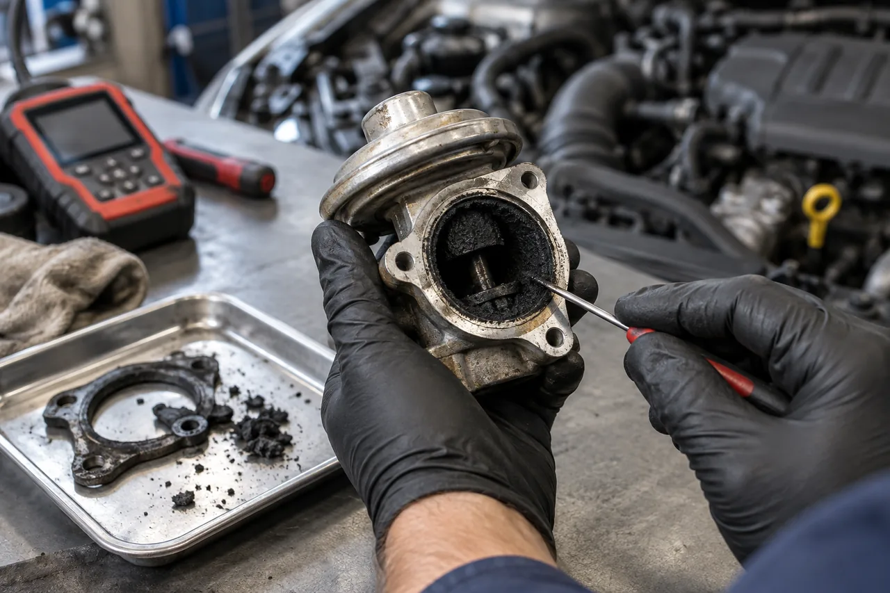
The short answer: prove the failed relationship before choosing EGR repair
An EGR valve should be cleaned or replaced only when testing shows that its movement, sealing, circuit, or metering is the cause of the failed system response. Low flow can come from blocked passages or a cooler; a circuit or position fault can come from wiring or power; rough running can come from flow at the wrong time or from a different air, fuel, ignition, or mechanical problem.
The fastest defensible path is to preserve the code and freeze frame, identify how the exact engine monitors EGR, command the system when supported, and compare requested movement with position and an independent response such as airflow, pressure, temperature, or engine operation.
What the EGR system is intended to do
Exhaust gas recirculation routes a controlled amount of exhaust back into the engine under selected operating conditions. That recirculated gas changes combustion conditions and is part of the vehicle’s emissions-control strategy. The exact layout can include an electronically or vacuum-operated valve, passages, a cooler, bypass hardware, pressure or temperature sensing, and software control.
Not every vehicle uses the same arrangement, and commanded EGR flow changes with load, temperature, speed, and emissions strategy. A diagram or generic replacement video cannot identify the correct part, access method, calibration, or verification for a specific engine. Start with the vehicle identification number, engine code, stored data, and applicable service information.
Symptoms can come from too much, too little, or incorrectly measured flow
A valve or passage that allows flow at the wrong time may contribute to rough idle, stalling, hesitation, smoke, reduced power, or hard starting. Restricted flow or a valve that does not respond may trigger a warning without producing an obvious driving symptom. Diesel and gasoline strategies differ, so a symptom list cannot establish which part failed.
Similar behavior can originate with intake or boost leakage, fuel or ignition problems, airflow measurement, exhaust restriction, wiring, vacuum supply, temperature sensing, or mechanical condition. Record the exact message, code family, engine temperature, load, speed, and whether the fault is steady or intermittent before clearing evidence.
An EGR code describes system performance, not automatically a bad valve
OBD monitors can evaluate an EGR system through commanded position, pressure change, temperature change, airflow response, or another manufacturer-defined method. A low-flow code may result from a restricted passage even when the valve moves. A position or circuit code may involve wiring, power, ground, reference voltage, a connector, or the actuator itself.
Freeze-frame and readiness information show when the monitor ran and whether testing is complete. Clearing codes resets useful context and may leave the monitor not ready until the correct conditions recur. Read all relevant modules and record pending, confirmed, and permanent information before deciding on a mechanical cleaning or replacement.
Match the observation to the next separating test
For a low-flow code with normal valve-position feedback, inspect and test passages, pipes, cooler restriction, pressure or temperature sensing, and whether commanded flow produces the expected change. For a circuit or position code, verify power, ground, signal integrity, connector condition, harness movement, and whether the actuator follows the command. For rough idle or stalling with unexpected flow, check valve seating, deposits, command state, and competing intake or fuel causes.
This is a decision matrix rather than a parts list: each observation should remove at least one plausible explanation. If the chosen test cannot distinguish a blocked path from a failed valve or an inaccurate sensor, it is not yet strong enough to support replacement.
Test command, movement, and actual system response
A diagnostic plan may inspect hoses and connectors, test power and ground under load, verify vacuum supply where used, command the valve with suitable equipment, compare requested and actual position, and observe the expected change in airflow, pressure, temperature, or engine operation. The useful signal depends on the system design.
A commanded movement that produces no measured flow can point toward restriction, disconnected plumbing, an inaccurate feedback signal, or a valve that moves externally but does not meter correctly. A flow response when no flow is commanded can suggest leakage or a valve that does not seat. The conclusion should connect command, response, and physical inspection.
Cleaning and replacement are different repair decisions
Carbon in an accessible passage may sometimes be removed according to an approved procedure, but cleaning is not automatically safe or effective for every valve, cooler, actuator, sensor, or coated component. Loose deposits can move elsewhere, solvents can damage electronics or seals, and a mechanically worn or electrically failed unit will not be restored by cleaning.
Replacement scope may include gaskets, seals, pipes, cooler connections, coolant, one-time-use fasteners, and access to other components. If a passage or cooler caused the flow fault, replacing only the valve may leave the code unchanged. The estimate should identify what evidence supports cleaning, valve replacement, passage service, or further testing.
Worked scenario: movement is reported but flow does not change
Imagine a vehicle with a low-flow fault where the scan tool reports the commanded EGR position moving, yet the expected airflow or pressure response barely changes. That evidence does not prove the replacement valve is the answer. The feedback may show actuator position while the gas path remains restricted, the cooler or passage may be blocked, or the response sensor may be inaccurate.
A useful next step compares command, independent system response, and physical path condition. If the valve is removed only after those tests, deposits and movement can be documented rather than discarded. The editorial judgment is to repair the failed relationship—valve, path, circuit, or measurement—not the noun printed in the code description.
What changes the scope and cost of EGR valve repair
The main scope drivers are engine layout, access, whether the EGR cooler shares the job, coolant drainage and bleeding, seized or damaged fasteners, pipe and gasket condition, deposit removal, wiring repair, required adaptations, and whether another fault caused the contamination. A price without those inclusions cannot be compared reliably with another estimate.
Ask which test confirmed the valve or restriction, whether passages and cooler operation are included, which seals and one-time-use parts will be replaced, whether coolant service is required, and what operating condition will verify the repair. These questions apply without publishing a made-up universal price.
Preserve emissions controls and safe working conditions
EGR hardware and software are part of the emissions-control system. Do not install a block-off plate, defeat device, misleading simulator, or calibration intended to bypass monitoring. Apart from legal and environmental consequences, removing a designed flow path can change combustion temperature, engine control, aftertreatment operation, and diagnostic behavior.
The system can involve hot exhaust, sharp shields, pressurized coolant, moving belts, difficult fasteners, and limited access. Allow the vehicle to cool and use the exact procedure, protective equipment, torque values, and replacement hardware. A general guide cannot determine whether a particular reader has a safe workspace or the required test equipment.
Verify the repair through the monitor’s real operating conditions
After repair, confirm connector and hose routing, leakage, coolant level when the circuit was opened, and any required adaptation or initialization. Recheck commanded position and the system response that originally failed. A warning light turning off after codes are cleared is not proof that the monitor has evaluated the repair.
Complete the manufacturer-defined operating conditions or a safe equivalent road test, then check pending and confirmed faults and readiness status. If the fault returns, preserve the new freeze-frame information. A different operating condition can reveal a remaining restriction, intermittent circuit, inaccurate sensor, or another engine problem rather than a defective replacement valve.