
Transmission diagnosis
Reproduce and measure the shift concern before choosing service, repair, or replacement
For a SeaTac transmission concern, first define the exact shift, temperature, load, speed, and delay or vibration that changed. Fluid, leaks, electrical supply, sensors, software, hydraulic control, clutches, gears, bearings, mounts, axles, tires, or engine operation can overlap; a code or fluid service alone does not define the repair.
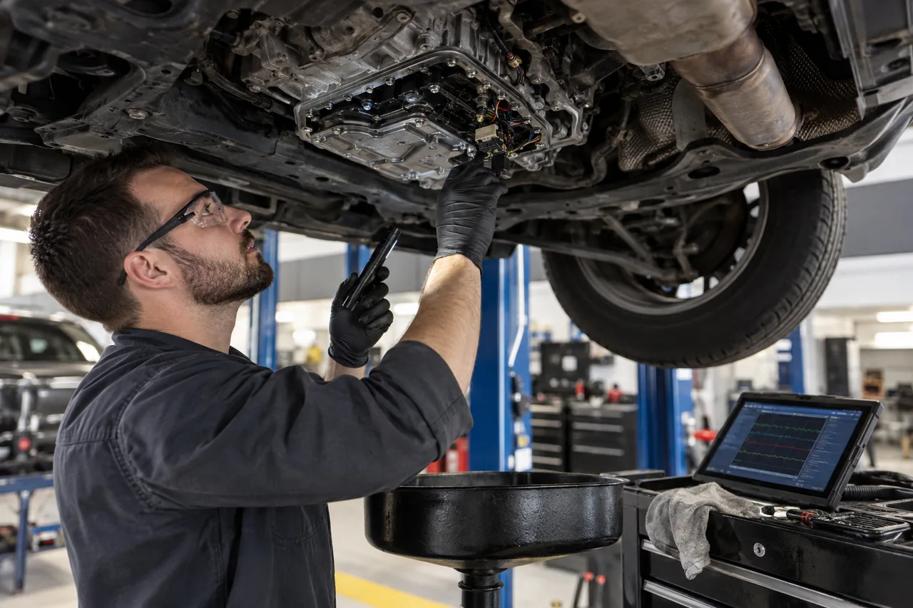
Quick decision: maintenance, diagnosis, or major repair
Choose maintenance when the exact unit, approved fluid, schedule or supported condition, and correct level procedure justify it without an active fault being misrepresented as “fixed.” Choose diagnosis when engagement, shift quality, warning status, leakage, noise, vibration, or temperature has changed. Major internal repair or replacement is justified only after external controls, fluid condition, connected driveline systems, and measurable internal evidence define that scope.
A local search for transmission service often hides these different jobs. The useful next action is to describe the event and authorize the stage that can distinguish them, not to select a flush, rebuild, or replacement from the search phrase alone.
Stop driving when engagement or fluid loss becomes unsafe
Stop safely for sudden loss of drive, unexpected movement, failure to hold Park, inability to select the intended direction, heavy grinding, smoke, a strong burning odor, rapid fluid loss, or a warning accompanied by severe reduced performance. Do not repeatedly shift between ranges or increase throttle to force engagement.
Record the exact message, selected range, actual response, engine speed, vehicle speed, temperature, incline, cold or hot state, and events before the problem. A vehicle with no drive may still roll; use the parking brake and safe recovery procedure. Towing method depends on drivetrain and manufacturer instructions because rotating an unlubricated or faulted unit can add damage.
Describe the event instead of using “transmission slipping” broadly
Separate delayed engagement from engine-speed flare during a shift, torque-converter shudder, clutch chatter, harsh engagement, repeated hunting, wrong-gear operation, manual-clutch slip, grinding into gear, vibration under load, and a driveline clunk. Note the specific shift, throttle, road grade, steering angle, drive mode, trailer load, outside temperature, and whether the condition follows a cold soak or heat soak.
Engine misfire, reduced power, incorrect load information, brake or stability intervention, mismatched tires, wheel-speed faults, damaged mounts, axles, driveshafts, differentials, and software strategy can imitate or influence a transmission complaint. Reproduce the concern safely and identify which system changes at the same moment before authorizing internal repair.
Scan complete vehicle data before clearing adaptations or codes
Read transmission, engine, brake, transfer-case, body, and network modules as applicable. Preserve confirmed, pending, history, and communication codes, freeze frame, temperature, input and output speed, selected and commanded range, gear ratio, pressure command, clutch or shift timing data, voltage, and adaptation information available for the unit.
A gear-ratio, pressure, solenoid, speed-sensor, or communication code defines a monitored condition, not automatically a replacement part. Low voltage or a shared network fault can create secondary transmission messages. Clearing records or resetting adaptations before capture may remove evidence and alter shift behavior, making the original concern harder to reproduce.
Fluid level, specification, temperature, and leakage are inseparable
ZF notes that the manufacturer procedure is essential for checking transmission oil and that many modern units require a defined operating temperature, level surface, running condition, gear sequence, or diagnostic system. Too little or too much fluid can affect aeration, pressure, lubrication, cooling, and shifting. A fluid that appears near an opening at the wrong temperature or operating state is not a valid level result.
Identify the exact transmission and approved fluid, not just vehicle model or fluid color. ZF describes transmission fluids as matched to specific units and provides application lists. Trace leaks to the first fresh source—pan, connector sleeve, cooler, line, seal, vent, case, transfer case, or engine fluid can be confused. Correct the cause and fill method rather than topping off repeatedly.
A fluid service is maintenance or a supported intervention—not a rebuild
Fluid and filter service may be appropriate according to manufacturer information, history, contamination, operating conditions, or a supported diagnostic plan. It can restore the correct level and material and remove serviceable debris, but it cannot replace worn friction material, repair a broken hard part, reseal every internal leak, correct damaged electronics, or undo heat damage.
Discuss drain-and-fill, pan and filter replacement, exchange, or other procedures by exact unit. “Flush” is not one universal operation, and chemicals or machines must not override the manufacturer method. Inspect the pan, magnets, filter, fluid, and debris when accessible, document the finding, and avoid promising that new fluid will cure an established mechanical failure.
Worked scenario: delayed engagement only after a cold soak
Consider a vehicle that engages Drive slowly after sitting overnight but behaves normally when warm. The test plan should reproduce the cold condition, record engagement time and temperature, confirm battery voltage and module data, check fluid level by the exact procedure, inspect leakage, and compare command, pressure or fill information available for the unit. A warm road test alone can miss the complaint.
If fluid is low, the repair still needs a leak source and a correct refill; if level and control data are normal but internal fill behavior is not, staged hydraulic or internal diagnosis may be justified. The editorial judgment is to preserve the cold evidence before service or adaptation resets change it.
Test commands, circuits, hydraulics, and mechanical response together
Electronic testing can include power and ground under load, connectors, harness paths, network communication, speed and temperature sensors, range input, solenoid or actuator command, and software applicability. Hydraulic testing may involve commanded versus actual pressure, fill time, pressure taps, leak checks, or a valve-body and mechatronic procedure specific to the design.
Mechanical evidence can include ratio error, debris, clutch or band application behavior, bearing or gear noise, torque-converter operation, manual-clutch release, synchronizer behavior, and transfer-case or differential checks. ZF describes professional diagnosis as fault-memory interpretation and relevant static and dynamic vehicle data before cleaning, disassembly, repair, and final testing. The evidence should determine which stage is justified.
Define the repair option and every transferred component
Possible scopes include an external leak or circuit repair, service, sensor or harness work, valve body or mechatronic repair, torque converter, clutch, targeted internal repair, complete rebuild, used unit, remanufactured unit, or new assembly. Each has different included parts, contamination control, programming, warranty, core, history, and verification assumptions.
The estimate should identify the exact unit, removal and installation, cooler and line handling, converter or clutch, mounts, seals, hardware, fluid quantity and specification, filters, software, coding, adaptations, transfer components, taxes, core return, and warranty labor. If internal inspection can change the scope, define the authorized teardown stage, measurement evidence, stop point, and approval process in advance.
Contamination and the cooler circuit can determine durability
A failed clutch, bearing, converter, pump, or hard part can distribute debris through the transmission, valve body, cooler, lines, and shared lubrication paths. Installing a repaired or replacement unit without following the specified cooler inspection, replacement, flushing, flow test, or contamination procedure can send debris back into the new work.
Not every cooler design can be cleaned effectively, and not every unit shares the same path. Document what failed, what debris was found, which connected components are included, and how cleanliness will be verified. Also correct engine-cooling, electrical, mounting, driveline, or software problems that contributed to heat, load, vibration, or control failure.
Programming, adaptations, and learning require a reasoned process
Some units require software, coding, component protection, clutch or range calibration, fill procedures, or adaptation after repair. Other adaptations should not be reset casually because they describe compensation learned over time. Use the exact service procedure and a stable electrical supply; state which reset or learn was performed and why.
Initial shift quality may change during a defined learning period, but “it needs to learn” should not excuse slipping, flare, pressure faults, leakage, severe harshness, or an unsafe result. Monitor temperatures, ratios, pressures or fill data where available and compare the outcome with the pre-repair evidence. If a relearn cannot complete, diagnose the blocking condition rather than repeating resets.
Verify cold, hot, loaded, and leak-free operation
Before movement, confirm the correct fluid level under the required conditions, no leaks, secure connectors and lines, completed programming or calibration, normal range indication, brake interlock, and safe engagement. A road test should cover the original condition and an appropriate range of shifts without exceeding traffic or vehicle limits.
Recheck after operating temperature and a heat cycle: engagement time, shift timing and feel, ratio, converter or clutch behavior, noise, vibration, temperature, warning status, stored faults, fluid level, and leakage. Document which verification is immediate and whether a cold-start follow-up remains. A successful repair explains the original fault and demonstrates controlled operation rather than relying only on a cleared code.